

Information Technology (IT) Pioneers
Retirees and former employees of Unisys, Lockheed Martin, and their heritage companies
30-bit Computers, Chapter 52
1. Introduction to our 30 Bit ISA Computers
This 30-bit Instruction Set Architecture (ISA) is the longest LEGACY thread. This 30-bit line started with the AN/USQ-17 lab/shipboard systems in the mid-fifties. The last 30-bit production unit delivery was the 499th CP-901 in 1992, a 35-year history of manufacturing equipments with this basic architecture.
This page provides general data about all of the 30-bit computers with descriptions contributed by engineers of the LEGACY companies. Contributions from all interested parties are welcome. Note Don Mager's 1230 article. Of historical note, the Univac/Sperry/Unisys 490 series of commercial computers also used this same basic 30-bit ISA. For researchers; we've copied many scanned technical manuals and booklets from the bit savers website, linked in section 5 below.[lab]
1.1 User feedback
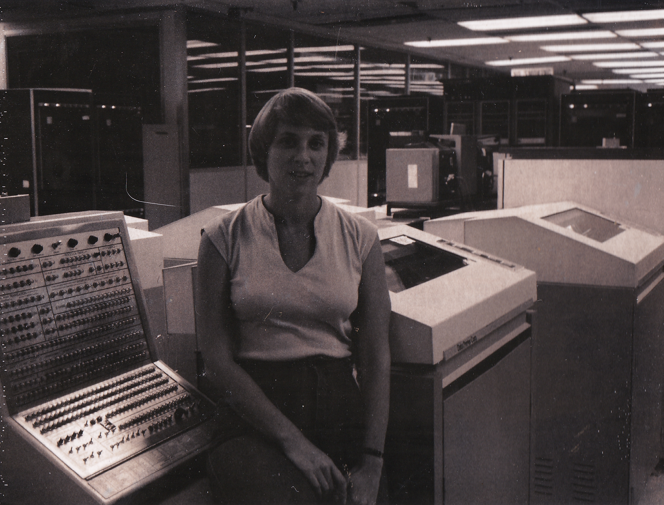
From Betsy Wilson, JPL employee 1975 to 2012. (Added December 2023)
I came to work at JPL in 1975, for the Voyager project (not called Voyager back then). The 1530s were used for Viking, Voyager, and Galileo space programs. For Voyager and Galileo they were part of a multi-computer system, comprising of the 1530, a Univac 1219, and several Modcomps. They did some early 'in the stream' telemetry processing, including frame synchronization, decoding for error detection and correction, extraction of engineering, science, and imaging data to be sent to other computers for further processing (including actual image creation), and decommutation of channels (sometimes called measurands or measurements). The 1219 was used to further process and display the measurements. The 1530 was replaced sometime in the early to mid 1980's by VAXes, then eventually by SUNs and similar UNIX-based machines. As you may or may not know, the Galileo high-gain antenna failed to open, reducing the bit rate from 134,000 bps to no more than about 100 bps, by using the low-gain antenna for the full mission. It had been determined even before launch that the rate of 134,000 bps was not manageable by the 1530 anyway, so plans were started to make some switch in CPUs before actual Jupiter operations.
 Anyway, for some reason I was searching the
web for the 1530 and found this chapter 53. I have fond but complicated
memories of using this machine. It had no terminal, we just debugged
using the console with the registers and memory accessed by 30
lighted binary switches. Clearing core was a long set of operations,
and booting used a paper tape. Output was tape and some electronic
links to the 1219 and Modcomps. We wrote in assembler that was
compiled by another machine and output into binary cards that were
then loaded into the 1530. The rest of the 1530 system was on a tape
(9-track I think, but
possibly 7). We could patch directly into it with binary cards.
Altogether much more work than later systems! I
was the only woman programmer of the 1530 as I recall at the time,
and I have one picture of me with that console. Anyway, I thought
somebody might enjoy these recollections. I retired as a principal
telemetry engineer from JPL in 2012, having mostly stopped
programming to just engineer the telemetry processing systems.
Anyway, for some reason I was searching the
web for the 1530 and found this chapter 53. I have fond but complicated
memories of using this machine. It had no terminal, we just debugged
using the console with the registers and memory accessed by 30
lighted binary switches. Clearing core was a long set of operations,
and booting used a paper tape. Output was tape and some electronic
links to the 1219 and Modcomps. We wrote in assembler that was
compiled by another machine and output into binary cards that were
then loaded into the 1530. The rest of the 1530 system was on a tape
(9-track I think, but
possibly 7). We could patch directly into it with binary cards.
Altogether much more work than later systems! I
was the only woman programmer of the 1530 as I recall at the time,
and I have one picture of me with that console. Anyway, I thought
somebody might enjoy these recollections. I retired as a principal
telemetry engineer from JPL in 2012, having mostly stopped
programming to just engineer the telemetry processing systems.
Betsy Wilson
2. Technologies:
The 30-bit equipment threads evolved from germanium transistor logic implementations to integrated circuits to small scale integration to medium scale integration silicon circuits. If vacuum-tube logic were the first generation, then transistors were the second, integrated circuits were the third and embedded microprocessors were the fourth generation. These units advanced from an 8 microsecond core memory cycle time to a 750 nano-second cycle time. The computers were used in shipboard environments, land based aircraft, submarines, a jet fighter, Marine battle field shelters, and FAA operations centers.
3. Computer Unit Summaries:
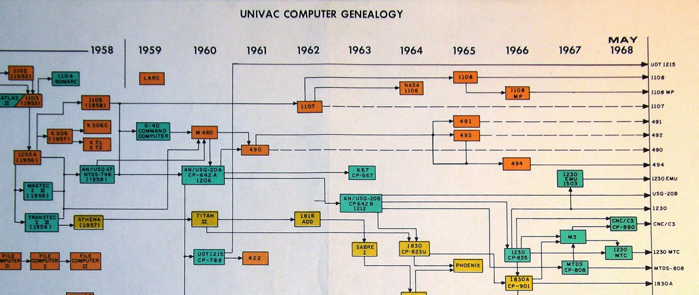
This clipped 1968 Genealogy chart shows that there were several 30-bit variations produced since beginning with the 1104 in the mid-50s. The orange boxes are commercial applications, types 491-494. The type 1100 series computer systems were 36-bit machines. The yellow boxes were either space or airborne machines. The type 1830A (nomenclature CP-901) had a 45 year operational life. Not shown on this chart is the Input/Output Processor (IOP) first delivered in April 1969 to the FAA's Air Traffic Control Program where it had a 40 year operational life!
3.1 1104
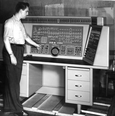 The 1104 used the 1103 logic design, reduced from 36 to 30 bits for the Bomarc missile guidance system prototype.
John Alton was one of the logic design engineers. Bob Blixt was the lead programmer, shown in this photo at the
right provided by Curt Nelson. Curt (William) Nelson was the power supply and installation engineer. Production
units were redesigned with silicon transistor logic and core memories. There were units installed at Patrick
AFB and Eglin AFB in the early 50's according to a an old
genealogy chart. Subsequently, the 1104 processors were
replaced with an version of the AN/USQ-20 computer system,
identified as the G-40 computer on some genealogy charts.
The 1104 used the 1103 logic design, reduced from 36 to 30 bits for the Bomarc missile guidance system prototype.
John Alton was one of the logic design engineers. Bob Blixt was the lead programmer, shown in this photo at the
right provided by Curt Nelson. Curt (William) Nelson was the power supply and installation engineer. Production
units were redesigned with silicon transistor logic and core memories. There were units installed at Patrick
AFB and Eglin AFB in the early 50's according to a an old
genealogy chart. Subsequently, the 1104 processors were
replaced with an version of the AN/USQ-20 computer system,
identified as the G-40 computer on some genealogy charts.
{from the internet: BOMARC (Boeing Michigan Aeronautical Research Center) was a Cold War-Era Air Force nuclear missile site. The missiles were supersonic ground-to-air weapons designed to destroy attacking aircraft and airborne missiles. The facility, one of eight located around the country, east of Route 539 in Plumstead Township, N.J., was operated by the Air Force from 1959 until 1972.}
1104 Information:
Main memory - CRT Electrostatic 1024 words, 30 bits Mass storage – magnetic drum 16,384 words
Programming – minimum access [Sequential instructions are
placed/spaced on the drum such that each is about to travel
under the read heads as it is needed.]
![]()
3.2 Q-17:
The AN/USQ-17 was the
development baseline for the Naval Tactical Data System
creation. Six units were delivered in the mid '50s -
used aboard a few ships as system concept demonstrations. The
first three S/Ns resembled a horizontal deep freeze unit and
used an external operator/maintenance panel. The second
three S/Ns looked like an upright freezer, had the
operator/maintenance panel inside the door. The logic cards
used germanium transistors.
This computer design had two 'processing
elements', i.e. the primary ISA execution logic and a separate
free running input/output controller. Other machines had
to use a main program sequence to transfer words in or out of
the computer. Another innovation was that this ISA
implemented a repeat instruction, which would cause the
following instruction to repeat with operand fetch/store
indexing until either a count completed or a comparison criteria was met. The result was that only operand
memory fetches were needed instead of alternating instruction
and operand fetches. {Editor's note: this repeat
instruction note info from the M-460 manual at the Charles
Babbage Institute. The M-460 was the RRU type number
for the Q-17.}
Photo at the left from Curt Nelson shows Jim Thorton with a
Q-17 chassis extended upward. Mr. Thorton and
Seymour Cray presented an M-460 paper at a conference, the
photos in that paper looked just like the unit at the
left. [lab]
See section 1.1 of
https://vipclubmn.org/Articles/Erdrich1st.pdf.
AN/USQ-17 (NTDS) Characteristics:
Customer - BUSHIPS Environment - Laboratory First Delivery
- Spring 1958 Quantity built = 6
Vol/Ft< sup>3 =
54 Wt/Lbs =
2,200 Pwr/Wts =
2,500 Mem/Cyc = 8
usec Mem/Cap = 32k core
I/O rate =
0.50 kw/sec I/O channels - 18 input
and 12 output
From Curt Christensen Q-17
It seems that most historians are proceeding from the
book "When Computers Went to Sea" and the statement of the
courageous decision to redesign the Q-17 to get to the Q-20. I
find this to be curious because earlier in the book the author
discussed the same problem the "17" had with industry changing
performance of parts; only he reported it as the problem
Hughes had with fuzzy lines. To solve those problems they had
to get the vendors to stop changing the components
performance.
The practice at that time was generally to
buy parts from a company via their part number; for the "17"
the key was the SB100 transistor. [John Alton still has one in
his desk at home.] Seymour Cray came up with a design that
used the slow discharge of the unit when it was turned off.
The" redesign" of the "17" happened because the vendor
improved the SB100 component to turn off quickly and as a
result they would no longer work in the "17", thus there was
no choice as to what to do. The decision thus was for a new
design that resolved all the functional problems described as
result of tests done on the "17".
![]()
3.3 M-460:
The M-460 is a diachotomy, Dom Mager and Ernie Lantto both claim that it was a paper design yet Glen Johnson had written that Winnipeg had produced printed circuit cards for the M-460.
3.4 Q-20:
At that time the Navy Program office consisted of Vern Leas Program Manager, Florence Johnson his secretary, Bernie Eklund, and myself - Lyle Franklin. As the contract called for 16 units and there was no prototype. The service test unit, Serial 16, was built first and was the prototype. These had the maintenance panel inside the door, the cooling system didn't work well when ever operators or field service engineers needed access so after these units. Vern reported to Bob McDonald. Bob told Vern that he had been given a very big club but if he used it he'd be through. [Lyle Franklin]
The Q-20 system included the CP-642 computer - project started in September 1959 with the first unit delivery in October 1960. [E.S. Lantto]
3.5 The CP-642A [UNIVAC Type 1206]
This computer was the first NTDS
production computer installed into ships for operations.
Aboard ship, these units were cooled with a water chiller and
air re-circulated within the unit. This model was also
spun off to start the commercial 490 series of
computers. The first 17 were labeled XN1 through XN17,
the maintenance panel was mounted atop the unit. This
unit also implemented a 'real-time' clock with an accuracy of
1khz. The full machine had 3800 cards, approximately
1.5" x 2.5" each. These units used germanium
transistors. See section 1.2 of
https://vipclubmn.org/Articles/Erdrich1st.pdf.
The CP-642A computer was part of the AN/USQ-20(V) system.
Other USQ-20 system components were the RD-231A paper tape
reader/punch, or the RD-237 typewriter, or the RD-243 magnetic
tape unit, or the UGC-13 teletypewriter, or UGC-6
teletypewriter, or PU-491 Motor-Generator, or ...
Mr. Ed Thelen has created a web site with much more information about the 642A and 642B using information from the Computer History Museum, http://ed-thelen.org/comp-hist/univac-ntds.html . [lab]
CP-642A Information - project started Jan '61:
Customer - BUSHIPS
Environment - Shipboard First Delivery
- September 1961 Quantity built =
142
Vol/Ft< sup>3 =
54 Wt/Lbs =
2320 Pwr/Wts =
2000 Mem/Cyc = 8
usec. Mem/Cap = 32k core
I/O rate =
30 kw/sec I/O channels - 14 duplex
-15v
![]()
3.6 The CP-642B
UNIVAC type #1212 was a complete redesign from the 642A starting in
March
1961. The primary improvement was reducing the memory
cycle time from 8 microseconds to 4 microseconds and use of
silicon versus germanium transistors. Sometimes called
the 20B computer, another innovation for this unit was a 'film
memory' drawer. The film memory was used to store the
index registers and I/O addresses which had been mapped onto
core memory addresses in the 642A.
 A 32-word
bootstrap card was mounted atop the mated-film stack.
Univac delivered 241 of these units to the Navy and Foreign
Military Sales (FMS).
A 32-word
bootstrap card was mounted atop the mated-film stack.
Univac delivered 241 of these units to the Navy and Foreign
Military Sales (FMS).
There were
over 40 variations of the 642B delivered; solid mounted or
shock mounted, water cooled or air cooled, and inter-computer
or normal channels in four channel groups. UNIVAC
drawing number 4051212-xx documented the specific
configurations, for example P/N 4051212-36 was a water cooled,
shock mounted unit with four -3V normal channels and twelve
-15v inter-computer channels. Shown here is
a 642B in the Inertial Guidance Room of the CV-41, USS Midway
- now a San Diego Harbor Museum. Thanks to Jon Simon. [lab]
CP-642B Information - project started March 1961:
Customer - BUSHIPS
Environment - Shipboard First Delivery
- February 1963 Quantity built =
241
Vol/Ft3 = 54 Wt/Lbs =
2400 Pwr/Wts =
2000 Mem/Cyc = 4
usec. Mem/Cap = 32k
I/O rate
= 250 kw/sec I/O channels - 16 duplex
@ -15v or -3v in 4 channel groups. Inter-computer in 4 channel
groups. An internal real-time clock counted a one binary tick every 1/1024th of a second.
Software available - FORTRAN, CS-1, SYCOL, SYMON, and
Executive.
![]()
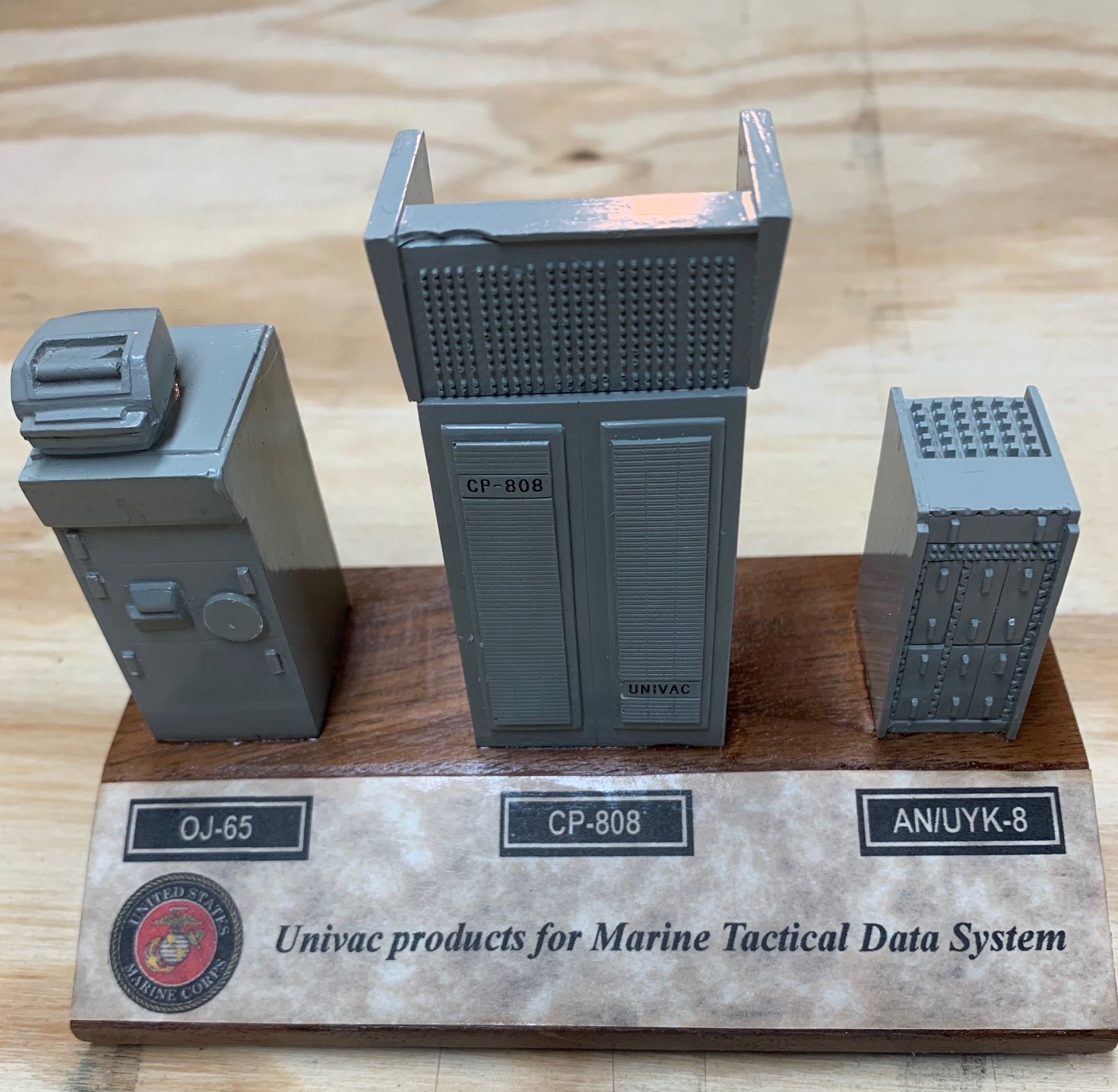 3.7 CP-808, UNIVAC Type # 1213.
The Marine Corps specified the 30-bit ISA for a shelter based Marine Tactical Data System (MTDS). The CP-808 was delivered into this system. The power supply for this computer was external to provide operation from 400 Hz three phase power used in conjunction with the Marine shelters for their communications systems. Reference the Marine Systems page for more information. [lab]
CP- 808 Information - project started July 1964:
Customer - USMC
Environment - Shelter First Delivery -
September 1964 Quantity built =
19
Vol/Ft3 = 54 Wt/Lbs =
1750 Pwr/Wts =
3500 Mem/Cyc = 2
usec Mem/Cap = 32k
I/O rate = 250
kw/sec I/O channels - 16 duplex; -3v
or -15v.
Software available - FORTRAN, CS-1, SYCOL, SYMON,
and Executive
![]()
3.8 CP-823 (Type 1830)
This unit was
to be the first flying 30-bit machine, developed for the Naval Air Development Center at Johnsville, PA. This unit is
now in the hands of Todd J. Thomas after being in storage for
almost 40 years. Mr. Thomas' photo of the
various units is shown here.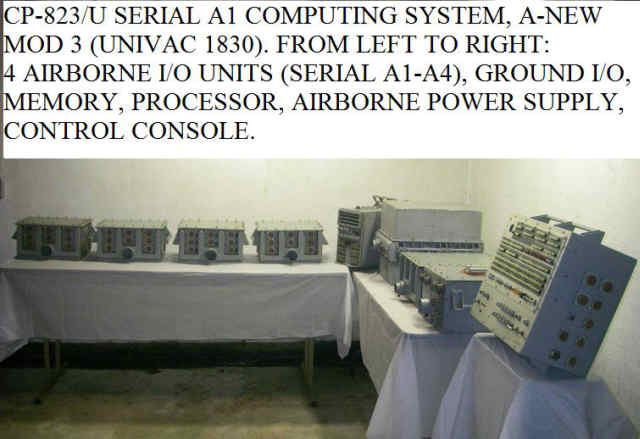
The preliminary Anti-Submarine Warfare (ASW) software development started with this unit, see the Systems, Airborne items written by Bob Blixt and Jim Rapinac. Pete Olson was one of the logic designers, George Kydd worked on the I/O units, Ray Bowar did some of the memory design, M. R. Clements was the marketing manager. This unit used some of the same integrated circuit flat packs as were developed for the 1824 computer. To minimize development costs, some of the logic card types used in the control console and ground support unit were copied from the CP-667. [lab]
CP-823/U (1830) Information - project start November 1963:
Customer - NAVAIR Environment -
Airborne First (only) Delivery - June
1965 Quantity built = 1
Vol/Ft3 =
4.68 Wt/Lbs =
224 Pwr/Wts =
830 Mem/Cyc = 4
usec Mem = 28k core & 4 k film
I/O rate = ? I/O channels were 8 duplex;
-3v. The contract value was almost $2M.
![]()
3.9 1830 Phoenix - project start November 1964:
The logic boards from the CP-823 were repackaged into a rack mountable chassis for use in a classified system aboard an F-111. My first job after getting my BEE degree in June 1966 was checkout of these three machines. The acceptance testing of these units was done in Plant 2, under the observations of a government representative. The computers were connected to a 1532 I/O console, the acceptance test program was patched to print out 'OK' every 10,000 times through the program- about every 15 minutes. The processor and I/O circuitry were in one 1/2 ATR chassis while the 16k memory was in a second 1/2 ATR chassis. The design allowed for connection of a second memory chassis. After completion of checkout on the third unit, I was assigned to logic design group working on the CP-901. [lab]
1830 Phoenix Information:
Customer - AIR FORCE via Hughes Aircraft.
Environment - Airborne First Delivery
- March 1966 Quantity built = 3
Vol/Ft3 = ?
Wt/Lbs = ? Pwr/Wts = ?
Mem/Cyc = 2 usec Mem/Cap = 16 k core
I/O rate
= I/O channels 8 duplex; -3v.
The three Phoenix 1830 computers were delivered to Hughes Aircraft in LA, the Phoenix Prime Contractor, for test and evaluation. NADC was the Phoenix program technical manager.
We lost the next phase of the program due to schedule and
technical risks in converting the 3 rows of PC cards in the
1830 P-3C chassis to a 2 row chassis to fit the Phoenix system
configuration. I think Litton won the contract. Hope this helps! Rapp
![]()
3.10 Univac type # 1230 - by Don Mager: (Apollo)
The 1230 computer was developed for NASA, to be used for
all telemetry data processing for the Apollo mission. A
total of 39 computers were eventually delivered to NASA.
We started the design of the 1230 in the fall of 1964 and
delivered the first unit July, 1965. Bob Oulicky
designed the I/O section, Glen Kregness designed the
arithmetic section and Don Mager designed the control
section. Although the 1230 was sometimes referred to as
the Modified 642B, it was a total new logic design utilizing
642B logic pc cards, 1219 memory components, the first "mated
film" memory for the control memory, and it was housed in a
standard 642B cabinet. [dvm]
The
instruction set was the standard 30 bit repertoire with
several new instructions to address the increased memory
size. Although the main memory was only twice as fast (2
micro-seconds) versus the 642B's 4 u-sec, the overall
performance approached 4 times that of the 642B. This
was accomplished by the control section being capable of over
lapping instruction and operand fetches to/from the two, 16k
each, memory banks. I believe this was the first Univac
Defense Systems Division (DSD) computer to have this
capability. Another interesting feature was the
capability to expand the memory, in an adjacent cabinet, to a
maximum of 264k words - the first time we went beyond
32k. Also unique was the asynchronous operation of the
external memory versus the synchronous memory operation of all
the earlier DSD computers. One of the challenges with
the external memory was dealing with the large number of
connections without changing the 642B cabinet design.
Necessity being the mother of invention, the number of data
path wires was reduced by 50% by sending the data
bi-directionally over the data paths and I was subsequently
granted my first computer related patent* for this method - a
technique that today is ubiquitous. [dvm]
October, 2019
recollections from Dick Erdrich: Lowell, I was assigned to
engineering for the initial checkout and was tasked by Don
Mager with selling unit No. 1 one to NASA. After that I
supported qualification testing and final checkout in Plant 3
which was a common thing for Field Service troops to do when
not traveling.
I did make one trip to
Goddard Space Flight Center to check out an intermittent
problem that was creating some problems between the hardware
guys and the programmers. The only time I could get on the
system was at night so I ended up working 12 midnight to 7 in
the morning. After spending 5 nights starring at a scope and
varying the trigger levels I got a look at what was happening.
An interrupt (occuring asynchronously) had generated a voltage
spike that, after passing through 4 levels of logic, had been
expanded to a runt pulse which locked out the interrupt
without having recognized it. I found a signal that would mask
this runt pulse and allow the interrupt to be recognized
during the next scan. There was an "and" gate available so I
put in a change and started it up.
I ran the system for 2
nights with no problems and the programmers did their day time
testing with no problems so I put the change into the second
1230, declared victory and got out of Dodge.
Bob Oulicky had been
responsible for the I/O design which was largely a carryover
from the CP-642B and he never could understand what the
problem was and how this change fixed it but it's hard to
argue with success.
Cheers, Dick [rae]
As a near term follow on project, we developed the 1230 Expanded Memory Unit, almost an identical box with just memory chassis in it. This was simply called the 1230 EMU.
1230 - CP-855/UYK Information - project started December 1964:
Customer - NASA/Navy Environment -
Laboratory First Delivery - July
1965 Quantity built = 63
Vol/Ft3 =
60 Wt/Lbs =
2100 Pwr/Wts =
3500 Mem/Cyc = 2
usec Mem/Cap = 131k
I/O rate = 500
kw/sec I/O channels - 16 duplex; 3v or
-15v
Software available was: FORTRAN, SYMON, SYCOL, CS-1, and a Service Library
3.11 CP-890 - Univac Type #1836 by Dick Erdrich [rae] and Don Mager [dvm]
The CP-890 was a third generation computer design, it began in July 1966. {Editor's note - First generation used vacuum tubes, second generation used transistors.} What defined this generational step was the use of the Diode Transistor Logic integrated circuits. These were the P/N 7901000 and 7901001 Small Scale Integration flat packs used for all of the logic functions. All of the following computers, until the 1616, used the same basic DTL technology. These included the AN/UYK-8, 1530 Missile Tracking Computer, and the ARTS-III IOP as well as the AN/UYK-7 and AN/AYK-10 [the S-3A mission computer] 32-bit computers. [rae]
Don Mager did the
Engineering proposal, was the development project engineer,
and managed the team through delivery of the first six
units. John Bruder was the key memory engineer - this
unit had UNIVAC's first three wire core memory. Neil
Macrorie designed the I/O section. Jim Warwick did the
mechanical design. The power supply design to meet harsh
input power specifications was done by Bob Wyland. Dick
Erdrich did the processor logic desigh. Jack
Smith reported to Don as Project Engineer of the companion I/O
Buffer unit {Editor's note 4/13: This unit is the CV2342/UYK}. Ray Dombeck worked on the I/O Buffer
design, later was the CP-890 support engineering
supervisor. I, Don Mager, designed the control memory which
originally was to use the mated-film technology. I became
aware that the Minuteman project at Honeywell had developed a
16 bit memory cell. I sought management approval to use
it instead of the mated -film. After several arguments
among engineering management, Red Phillips intervened to
approve use of the 16 bit memory chip. About half way
through the design, it became evident that the power
consumption would be exceeded. I asked Jack Metzger to
determine the impact of running the logic circuits at 5.5
volts instead of the specific 6 volts. After an
analysis determined that the performance impact would be
nil, we set the primary Integrated Circuit voltage at 5.5
volts saving about 20% of the projected logic power - this
decision resulted in a cooler and more reliable
computer. [dvm]
The CP-890 was
specifically designed for SP-24 to replace the NAVDAC that was
aboard the Polaris boats. I had been told by Navy folks
that the mean up time of the NAVDAC computer very poor.
True or not, I don't know. I do know that there was a
very strong emphasis on reliability during our design. I
ended up by doing virtually all of the CPU design. Leroy Olson
was supposed to do the Control section and I was assigned the
Arithmetic section as this was the first implementation of a
30-bit floating point hardware algorithm. Leroy had
a chance to go into management and bailed out shortly after
the project started thus I inherited the remainder of the
design. Jack Metzger and Mel Wagner did the circuit
analysis for all of the logic and I/O modules. The
design rules were extremely conservative. It made the
job a lot tougher but the end result was a bulletproof
design. I did a study for SP-24 after production had
started and was able to increase the clock speed by 30% before
anything went bad. Of more interest to me was that after
I had fixed the limiting logic, a piece of my design in the
control section, I was able to increase the clock speed by 55%
before a number of things started showing up. The Navy
was happy with the results but never gave any thought of
increasing the clock speed in the fielded units. They
liked the reliability also. [rae]
The CP-890 could operate in
normal or expanded addressing modes. The expanded
addressing mode was adopted from the the NASA 1230
computer. In normal mode the P register was limited to
15 bits before rollover and the operand address was also
limited to 15 bits. In expanded addressing mode the P
Register was lengthened to 18 bits and operand address
generation used the upper 2 bits of y to address 3 Extension
Registers which concatenated a 5-bit constant to
the lower 13 bits of y resulting in an 18 bit
address. This was referred to as the 262K address
range. All of the production CP-890's were built with
only 32K of memory. The 1230MTC delivered to the Air
Force was a repackaged CP-890 but added an additional memory
chassis for a total of 65K. The ARTS-III IOP used the
same address generation architecture and most of the
instruction set of the CP-890 (no floating point). They
eventually did incorporate all 262K of memory and may have
added more. [rae]
The Navy never, as far as I know, seriously explored adding
more memory into the basic CP-890 box. We were aware of
the fact that they did roll in software processes as they were
needed but had made the decision to maintain the tape units
rather than adding memory to the CP-890.
[rae]
The mechanical shape
of this unit was unique to enable lowering through submarine
hatches.
 Although the extension registers gave the
design the capability to access 131k of memory and the chassis
could hold 65k, the units were delivered with only 32k words.
This unit's processing power and connected sensors
facilitated submarine navigation under the polar ice
cap. [lab]
Although the extension registers gave the
design the capability to access 131k of memory and the chassis
could hold 65k, the units were delivered with only 32k words.
This unit's processing power and connected sensors
facilitated submarine navigation under the polar ice
cap. [lab]
The
photo at the right was provided by Jack Lavers. Thanks
to Tom E. for identifying this CP-890 production management
team of Jim Knox, Victor Patriaz, Ray Dombeck, Jack Lavers,
Jerry Burnett, Myself, Chuck Mueller, Dave Young.
[lab]
I should note here that when I did the
Architecture for the Memory Processor to replace the CP-890 I
provided 24 bits of addressing. We delivered two 2
processors and a common memory rack containing 8 MB in each of
the Trident Memory Processors. Two processors could
easily share a common memory due to the presence of extremely
large Cache Memories in front of both processors.
Commercial processors at the time were only using level
1 caches (level 2 was not here yet) of 256 bytes. Each
Memory processor CPU had 256K bytes. That was all done in the
early 80's. [rae]
CP-890 Information - project started July 1966:
Customer - US Navy Environment -
Submarine First Delivery - October
1967 Quantity built = 197
Vol/Ft3 =
13 Wt/Lbs =
725 Pwr/Wts =
2150 Mem/Cyc = 1.8
usec Mem/Cap = 131k
I/O rate =
555kw/sec I/O channels - 16 duplex;
-3v or -15v
Testimonial From: Charles Parmele:
Message: I just have to say I loved
the cp-890. I was a Central Navigation Computer Tech on the
USS Daniel Boone and then the USS Florida before the Trident
commonality upgrade. I enjoyed working on them, using the flow
charts and logic diagrams, heck I didn't even mind adjusting
the memory currents. We, I retrained for the Trident 2
Navigation system I missed the old cp-890's even though the
Memory Processor units were easier to work with. I want to say
that you guys did great work, awesome design.
Thanks,
Charles Parmele
![]()
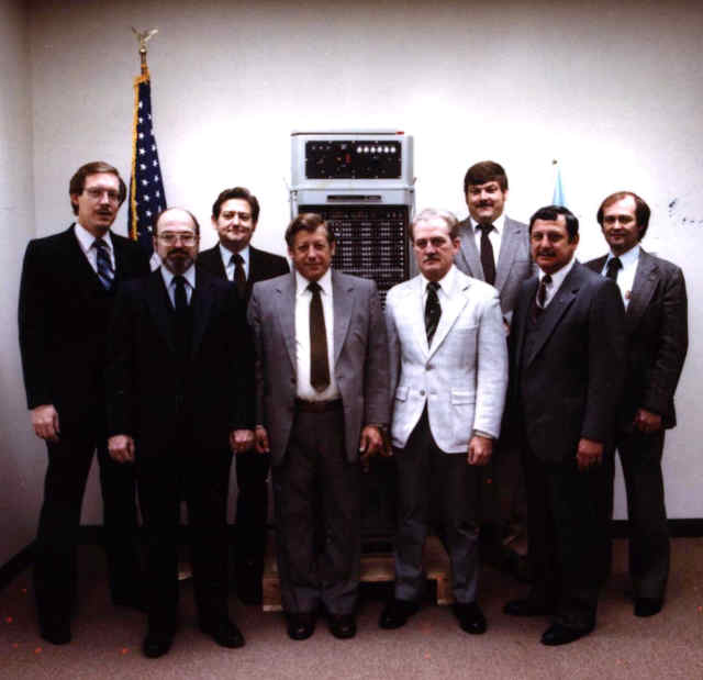
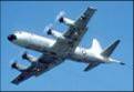
3.12 CP-901 - Univac Type #1830A.
 A design team led by supervisor, Ken Oehlers,
began development of the CP-901 (1830A) in April
1966. This unit was to be the core of the AN/ASQ-114
Anti-Submarine Warfare (ASW) Lockheed P-3-C aircraft. Others that I
recall were Finley McLeod (department manager), George Kydd
(I/O logic), John Bonnes (arithmetic), Ralph Mattie and
Al Schwartz [memory], John Grape and LeRoy Vick [power supply],
Dennis Paulinski [wire tabs], and me [PC board layout, mfg
interface, and test software support.] Field Service
Engineer, Jack Anderson, and Lowell flew on a P-3 to deliver
the first unit to the Naval Air Development Center in
Johnsville, PA. This design had several innovations:
A design team led by supervisor, Ken Oehlers,
began development of the CP-901 (1830A) in April
1966. This unit was to be the core of the AN/ASQ-114
Anti-Submarine Warfare (ASW) Lockheed P-3-C aircraft. Others that I
recall were Finley McLeod (department manager), George Kydd
(I/O logic), John Bonnes (arithmetic), Ralph Mattie and
Al Schwartz [memory], John Grape and LeRoy Vick [power supply],
Dennis Paulinski [wire tabs], and me [PC board layout, mfg
interface, and test software support.] Field Service
Engineer, Jack Anderson, and Lowell flew on a P-3 to deliver
the first unit to the Naval Air Development Center in
Johnsville, PA. This design had several innovations:
- A 512 word bootstrap [core-rope] program had a designed-in self test program to test basic arithmetic, memory, and I/O functions before initiating program load from either a magnetic tape or drum unit.
- It was the first to use a flat-pack integrated circuit [p/n 7901000 and 7901001] on a conduction cooled printed circuit card. Heat was conducted from the chip to the under chip heat sink to a 'T' bar at the top of the printed circuit card. A honeycombed heat exchanger pushed down on rows of these T-bars to transfer heat from the T-bars to air.
- The 16k word core memory chassis had three access ports. When the main frame was configured with three or four memory chassis, the logic design would access up to three memory banks simultaneously - an I/O transfer, an operand fetch or store, and the next instruction fetch.
- A set of sixteen 6-bit page registers to extend the memory addressing from the basic 32k words to 131k words plus a memory protect feature.
- A power failure detection mechanism to interrupt the program sequence so that critical data could be stored into core memory thereby facilitating quick mission resumption when the power returned to normal.
The first CP-901 was delivered to Johnsville, PA in September 1967 for software development. With S/N 499 delivery in 1993 this design was the longest production run of any other UNIVAC equipment! It is being phased out of operation by the CP-2044, an embedded emulation system whose development began in the early '90s. Although designed to address 131k words, the first 50 units were delivered with three memory chassis for 48k total. A fourth chassis was added to all units in the early '70s and in continuing production for a 64k operational system configuration. [lab]
AN/ASQ114 (CP-901) Information - project started April 1966:
Customer - NAVAIR Environment -
Airborne First Delivery - September
1967 Quantity built = 499
Vol/Ft3 =
6.9 Wt/Lbs =
~380 Pwr/Wts =
1400 Mem/Cyc = 2
usec Mem/Cap = 65k
I/O rate = 167
kw/sec I/O channels 16 duplexed,
+3v
![]()
3.13 1830B German Navy Computer.
In the late 60's the German Navy began development of a Fast Patrol Boat (FPB) for coastal defense. Hollandse Signaal Apparatan (HSA) [the military division of Phillips Global-Technique] and Univac submitted bids. The German Navy accepted the UNIVAC bid because they were quite happy with the performance and reliability of their 642B computers plus German sailors were familiar with the software development tools. Univac had proposed a shipboard version of the CP-901. There were four innovations for the first delivery in September 1970:
- Create a ship board cabinet to hold the airborne chassis.
- Adapt an I/O chassis using AN/UYK-7 printed circuit cards to provide the Mil-Std-1397 type A and type B interfaces [the CP-901 only had Type-C ANEW I/O channel.] We also used the UYK-7 'single window' core stacks for better sense amp operation.
- Adapt a type C channel to work as an External Specified Index with the HSA 24 bit I/O bus for their peripherals, and
- Medium Scale Integration (MSI) integrated circuit real-time clock and count-down clock to give the system response control at 100 kilo-hertz versus the 1 kilo-hertz real time clock used by previous 30 bit computers. [lab]
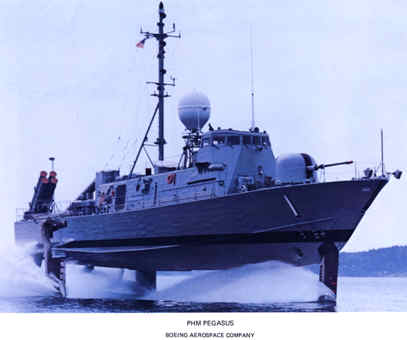 In the mid '70s
the US Navy began development of a Hydrofoil ship at
Boeing. They needed a small ships combat system so they
asked the German Navy for an adaptation of the FPB
system. The first ship, the Pegasus, received an 1830B,
a Telefunken display, an HSA radar, and our Italian 88mm twin
barreled anti-aircraft gun. As the Navy started testing
the system outside of Port Hueneme CA, the system went dead
when the gun was fired.
The Navy called St. Paul - Lowell was dispatched to help Bob Herbster (Field Service). The
next day, again at the Pacific firing range a plane flew over
towing a target drone, the ship fired, the system went dead.
I noted that both the program fault light and the power
fault light were lit. Then I asked to see the power
recovery program - there was none thus the reason for the
program fault light. Half an hour later I had written a
short power recovery program, plugged it into memory in
machine code, and restarted the system. The drone towing
plane came back, the gun fired, the display system blinked,
then kept tracking the drone. The power fault light was
lit on the computer but the program fault light was not.
The Navy was delighted - the Bob and I investigated the power
fault and found that the 400 HZ generator mounted on the aft
deck wasn't secured. When the gun was fired the
generator had jerked side to side causing it to briefly lose
its output. An innovation of the CP-901 carried forward
to the 1830B was detection of an impending power failure.
If the input power dropped below a specified level, a
power fault interrupt was sent to the processor. There
was sufficient residual power stored in the power supply to
allow a couple more seconds of operation. A power fault
program could quickly store status and critical data, then
upon recovery of power could restart where it left off.
The Navy built five more Hydro-foil ships - used an upgraded
systems with their AN/UYK-7 standard computer. [lab]
In the mid '70s
the US Navy began development of a Hydrofoil ship at
Boeing. They needed a small ships combat system so they
asked the German Navy for an adaptation of the FPB
system. The first ship, the Pegasus, received an 1830B,
a Telefunken display, an HSA radar, and our Italian 88mm twin
barreled anti-aircraft gun. As the Navy started testing
the system outside of Port Hueneme CA, the system went dead
when the gun was fired.
The Navy called St. Paul - Lowell was dispatched to help Bob Herbster (Field Service). The
next day, again at the Pacific firing range a plane flew over
towing a target drone, the ship fired, the system went dead.
I noted that both the program fault light and the power
fault light were lit. Then I asked to see the power
recovery program - there was none thus the reason for the
program fault light. Half an hour later I had written a
short power recovery program, plugged it into memory in
machine code, and restarted the system. The drone towing
plane came back, the gun fired, the display system blinked,
then kept tracking the drone. The power fault light was
lit on the computer but the program fault light was not.
The Navy was delighted - the Bob and I investigated the power
fault and found that the 400 HZ generator mounted on the aft
deck wasn't secured. When the gun was fired the
generator had jerked side to side causing it to briefly lose
its output. An innovation of the CP-901 carried forward
to the 1830B was detection of an impending power failure.
If the input power dropped below a specified level, a
power fault interrupt was sent to the processor. There
was sufficient residual power stored in the power supply to
allow a couple more seconds of operation. A power fault
program could quickly store status and critical data, then
upon recovery of power could restart where it left off.
The Navy built five more Hydro-foil ships - used an upgraded
systems with their AN/UYK-7 standard computer. [lab]
1830B Information - Projected started October 1969:
Customer - German Navy Environment -
Shipboard First Delivery - September
1970 Quantity built = 85
Vol/Ft3 =
10 Wt/Lbs =
481 Pwr/Wts =
1500 Mem/Cyc = 2
usec Mem/Cap = 65k
I/O rate = 167
kw/sec I/O channels 16 duplexed; -3v,
-15v, +3.5v
![]()
3.14 AN/UYK-8
The AN/UYK-8 was another update to the Marine Tactical Data System. This was part of their AN/AYS-20 system. It used the same cooling heat exchanger and card designs as were used in the CP-901. Bob Oulicky was the engineering manager of this project. The 16k word core memory chassis had four 4k word stacks. The support frame for for each word plane of the stack used a single window compared to the two window design of the CP-901. This moved the cores a bit closer together allowing shorter x & y drive lines as well as the inhibit and sense line being shorter. This allowed faster cycle times. The memory stacks had 32 core planes to provide a parity bit for each half word. These memory stacks were also used in the AN/UYK-7 and in the 1830B. This was a dual processor capable machine. [lab]
AN/UYK-8 Information - project started June 1967:
Customer - USMC
Environment - Shelter First Delivery
- January 1969 Quantity built =
22
Vol/Ft3 = 10.4 Wt/Lbs =
530 Pwr/Wts =
2000 Mem/Cyc =
1.5 Mem/Cap = 48k
I/O rate = 500
kw/sec I/O channels 16 duplex; -15v,
-3v, or =3v
![]()
3.15 UNIVAC TYPE #1530 -
MTC (Mobile Tactical Computer) was developed
for the U.S. Air Force.
 Generally called the 1230 MTC
because it performed many of the same system functions as the
1230 developed earlier for NASA. It used many of the
CP-890 printed circuit cards - but was a dual processor packed
into a single cabinet. See the Systems, Missile page for
more about this system computer. [lab]
Generally called the 1230 MTC
because it performed many of the same system functions as the
1230 developed earlier for NASA. It used many of the
CP-890 printed circuit cards - but was a dual processor packed
into a single cabinet. See the Systems, Missile page for
more about this system computer. [lab]
By Don Neuman
- We only sold one 1530 and that was to JPL in
Pasadena. That machine was in a 1230 mTc cabinet but it
was a single processor, single I/O with 64k of memory. [Both
memory drawers were used] When we closed the Kodiak tracking
station, JPL picked up the 1230 mTc and used it to pre-process
telemetry from the deep space projects.
Marketing
thought that the JPL image processing algorithms could be used
to start a new business line. They set up a lab using a
1616 computer and a digital scanner to process
mammograms. The guys had a good time looking at their
work but technology overtook us and cheaper, better, faster
image enhancement systems came on the market before we
finished the project.
The processor #1 of serial #1 1230 mTc had so many hand wraps
that it was intermittent. The Air Force requested us to
build a new processor chassis (Fixed price), and then transfer
all of the cards and power supplies form the old unit to the
new chassis. Manufacturing priced this effort by just
escalating the original cost to current dollars. When we
built the chassis, there was a $250,000 over run. The
price of gold had gone up from $32 per oz, to $800 per oz and
nobody had thought of this. [There was a lot of gold in them
there machines.]
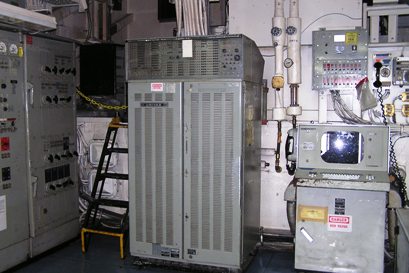
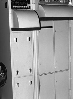
Later in the
program, the Air Force task us with replacing the 64k of core
memory with 256K of semiconductor memory. The new memory
was triple redundant with two parity bits in a new cabinet
[see picture]. We removed the core memory and taped the
air vents shut. Later the computer operators complained
about the noise level caused by the 400 Hz blowers. I
got to travel to all of the sites to analyze this noise. [What
a boondoggle.] My solution was a hood lined with
acoustic foam. [See picture -
right.]
The 1230 mTc did have
hardware-floating point. The mathematicians came to me
and said that the computer was wrong sometimes. After a
lot of analyzing, I found a runt pulse in the mantissa
rounding logic. Sometimes it would round and sometimes
it would not round. This small error affected the orbit
of the satellite we were working with.
1530 MTC Information - project started June 1967:
Vol/Ft3 = 12
Wt/Lbs = 800 Pwr/Wts =
4500 Mem/Cyc = 1
usec Mem/Cap = 262k
I/O rate = 555
kw/sec I/O channels - 16
duplexes. First delivery, February 1968.
![]()
3.16 ARTS III IOP -
Engineers from the CP-890, CP-901, and AN/UYK-8 design teams transitioned onto yet another 30-bit ISA project, i.e. creating a faster performance multi-processor for Air Traffic Control applications. The resulting Input Output Processor in several multiprocessor configurations was installed at 64 major airports for the Automated Radar Tower System. These ARTS III processors replaced the Arts I and Arts II 1218 processors. John Bonnes was one of the IOP design engineers. [lab]
ARTS III Input Output Processor (IOP) Information:
Customer - FAA Environment -
Ops Room First Delivery - April 1969 Quantity built =
110
Vol/Ft3 =
configuration dependent Wt/Lbs = configuration
dependent Pwr/Wts = configuration dependent
Mem/Cyc = 750 nanosec Mem/Cap =
I/O rate
= I/O channels 16 duplexed, +3v with a shorter
acknowledge pulse that the ANEW +3 v
interface.
3.17 ARTS III IOP Enhancements:
These were multiprocessor systems needed to handle the traffic at five airports in the New York City area. The hardware system could interconnect up to eight processors.
See the Systems, Air Traffic Control chapter for more information about the 40 year IOP life.
4. Repertoire Cards
Many of our retirees donated repertoire cards to the Legacy Committee. Keith Myhre scanned and catalogued these at the Lawshe Memorial Museum. The 1st copy was donated to the Charles Babbage Institute, a second copy of many was kept at the museum.
- ARTS III Quick Reference Data Card
- ARTS IOP Reference Data
- CP-642A, B, or CP-855 Utility Package
- CP-642B Utility Package Function Repertoire
- NTDS Compiling System (CS-1) Repertoire of Mono-Codes
- NTDS Unit Computer AN/USQ-20 Repertoire of Instructions
- NTDS Unit Computer Repertoire of Instructions
- UNIVAC 1206 Computer Repertoire of Instructions
- UNIVAC 1230 Computer Repertoire of Instructions
- UNIVAC 1830A Computer (CP-901) AN/ASQ-114(V) Instruction Repertoire
- UNIVAC 1830A Computer Instruction Repertoire
- UNIVAC 1830A Computer Modified Instruction Repertoire
- UNIVAC 1830B Computer Instruction Repertoire
- UNIVAC 8303 Input Output (IOP) Processor Repertoire of Instructions
- UNIVAC AN/UYK-8(V) Repertoire of Instructions
- UNIVAC CP-642B Computer Repertoire of Instructions (2 plastic cards)
- UNIVAC CP-642B Computer Repertoire of Instructions (Glossy)
- UNIVAC CP-642B Computer Repertoire of Instructions (Non-glossy)
- UNIVAC CP-642B Computer Repertoire of Instructions (Rounded corners)
- UNIVAC CP-823/U Computer Repertoire of Instructions
- UNIVAC CP-890 Computer Repertoire of Instructions
- UNIVAC IOP Repertoire of Instructions
- UNIVAC IOP Repertoire of Instructions (triple fold)
- UNIVAC MTC ADS Repertoire of Instructions
- UNIVAC Operating Instructions for CP-642 Teletype Debugging Functions
- UNIVAC UNISTAR IOP
Repertoire of Instructions

5. Technical Manuals
The bit-savers web site (http://bitsavers.informatik.uni-stuttgart.de/) has over 32,000 documents. We've copied the 30-bit ISA defense division documents (excludes the 490 series equipments linked from the Commercial computer page) and linked them hereunder for technology researchers ease of access.
- M-460 Computer Characteristics
- NAVSHIPS Technical Manual for CP-642B/USQ-20(V)
- PX 2846 Technical Description, CP-642B computer - July 1963
- PX3892 UNIVAC 1230 Military Computer Programming
- PX4292 CP-890 Military Computer - February 1967
- UNIVAC 1206 Military Real Time Computer General Description
- UNIVAC 1206 Military Computer General Description
- UNIVAC 1206 Military Computer Brochure
- U.S. Navy NTDS Technician Training Course
In this Chapter
- Introduction [left]
- User feedback.
- Technologies
- Computer summaries:
3.1, 1104 | 3.2, AN/USQ-17 | 3.3, M-460 | 3.4, AN/USQ-20 | 3.5, CP-642A | 3.6, CP-642B | 3.7, CP-808 | 3.8, CP-823 | 3.9, 1830 Phoenix | 3.10, 1230 | 3.11, CP-890 | 3.12, CP-901 | 3.13, 1830B | 3.14, AN/UYK 8 | 3.15, 1530 MTC | 3.16, FAA IOP | and the 3.17, ARTS III IOP Enhancements. - Repertoire Cards
- Technical Technical Manuals
Chapter 52 edited
11/10/2025.
![]() |
Home, Pg 1 |
Our Legacy, Ch 1 |
People |
Locations |
Engineered |
Computers |
Systems |
Contacts and Links |
Site Map, Pg 0 |
|
Home, Pg 1 |
Our Legacy, Ch 1 |
People |
Locations |
Engineered |
Computers |
Systems |
Contacts and Links |
Site Map, Pg 0 |
Copyright ©2025, LABenson for the VIP Club. All Rights Reserved; Hosted on www.webhostinghub.com since 2011.