

Information Technology (IT) Pioneers
Retirees and former employees of Unisys, Lockheed Martin, and their heritage companies
Special Purpose Computers, Chapter 58
1. INTRODUCTION
The U.S. Navy stopped development of military computers in 1994, they effected new computer system implementations with Commercial Off The Shelf (COTS) system implementations, sometimes referred to as embedded applications. We have had a major embedded computer contract [AN/UYQ-70] since 1994.
Even a little before then, a CP-901 replacement - the CP-2044 was built using Motorola 68040 microprocessor components. This early step made UNISYS and subsequently, Lockheed Martin a leading edge COTS systems competitor.
2. 1624
Bill Bauer was the project engineer for these units. [lab]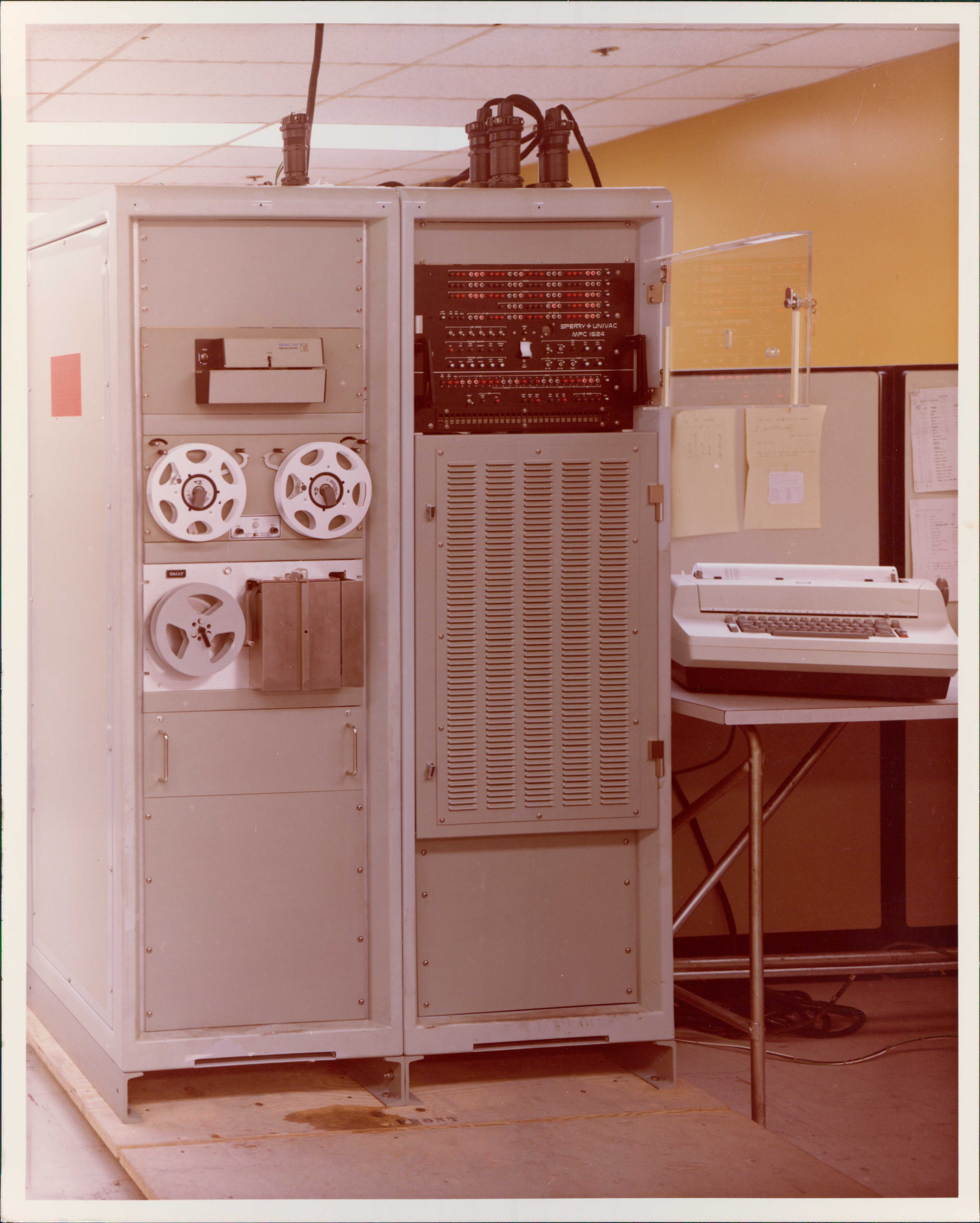
The Sperry type 1624 was designed to emulate the Computer Control Company DDP-24 machine using Micro-Program Controller techniques.
The DDP-24 was a van mounted general purpose digital computer, The
Computer History Museum has a unit in their
artifact collection.
Sperry
1624 units were packaged into commercial 19" racks then used for an Air Force
training program.
.jpg) Specifically, these units were part of a Minuteman status and command simulator used for training.
More about the launch computer at
cp18bit.html#UYK-11.
We at Sperry had developed and manufactured the computers used for the Minuteman missle system,
Specifically, these units were part of a Minuteman status and command simulator used for training.
More about the launch computer at
cp18bit.html#UYK-11.
We at Sperry had developed and manufactured the computers used for the Minuteman missle system, 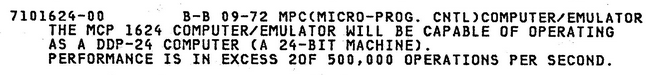
Data submitted by Lars Brinkhoff from the bit-savers' GS3577 document; photos from the Lawshe Memorial Museum via Keith Myhre.
3. Computer Types
3.1 Universal Digital Trainer (UDT)
The CP-788, UNIVAC type # 1215,was built using printed circuit cards from the 1218 computer, with many of the same salient features but 15 bits instead of 18; a lesser memory addressing capacity. The memory speed was 8 usec. Don Mager was the lead logic designer for this development. First unit delivered July 5th, 1962. This also had a commercial U-422 type designation. [lab]
Richard Wagner donated a technical manual to the Lawshe Memorial Museum, scanned for readers, UNIVAC Digital Trainer Tech Manual, 124 MB in size. Thanks to volunteer Keith Myhre (11/27/2020.)
U-422 The Southwest Museum of Engineering, Communications and Computation in AZ has a unit, https://www.smecc.org/univac_422.htm. Archivist Ed Sharpe would like to get it functioning, needs help.
 The
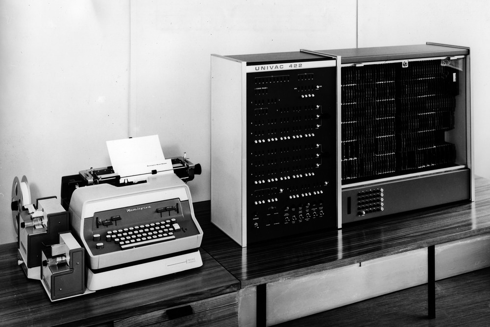
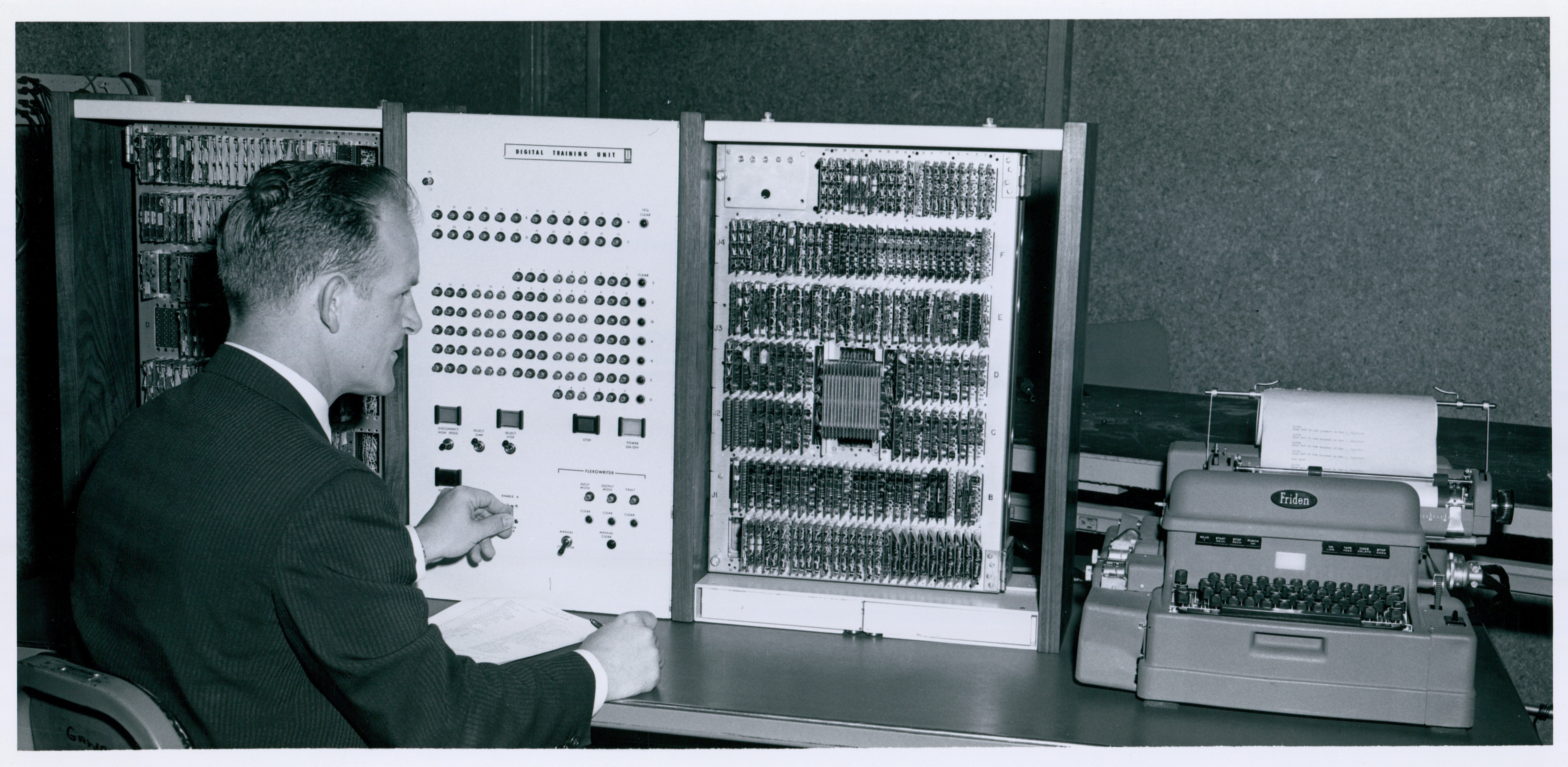
SMECC 422 unit is shown at the left, it has UNIVAC 422 on the
frame above the operator panel. At the left is a Remington
typewriter with a paper tape punch and a paper tape reader. This
photo came from Ed Sharpe, Archivist at SMECC.
The
SMECC 422 unit is shown at the left, it has UNIVAC 422 on the
frame above the operator panel. At the left is a Remington
typewriter with a paper tape punch and a paper tape reader. This
photo came from Ed Sharpe, Archivist at SMECC.
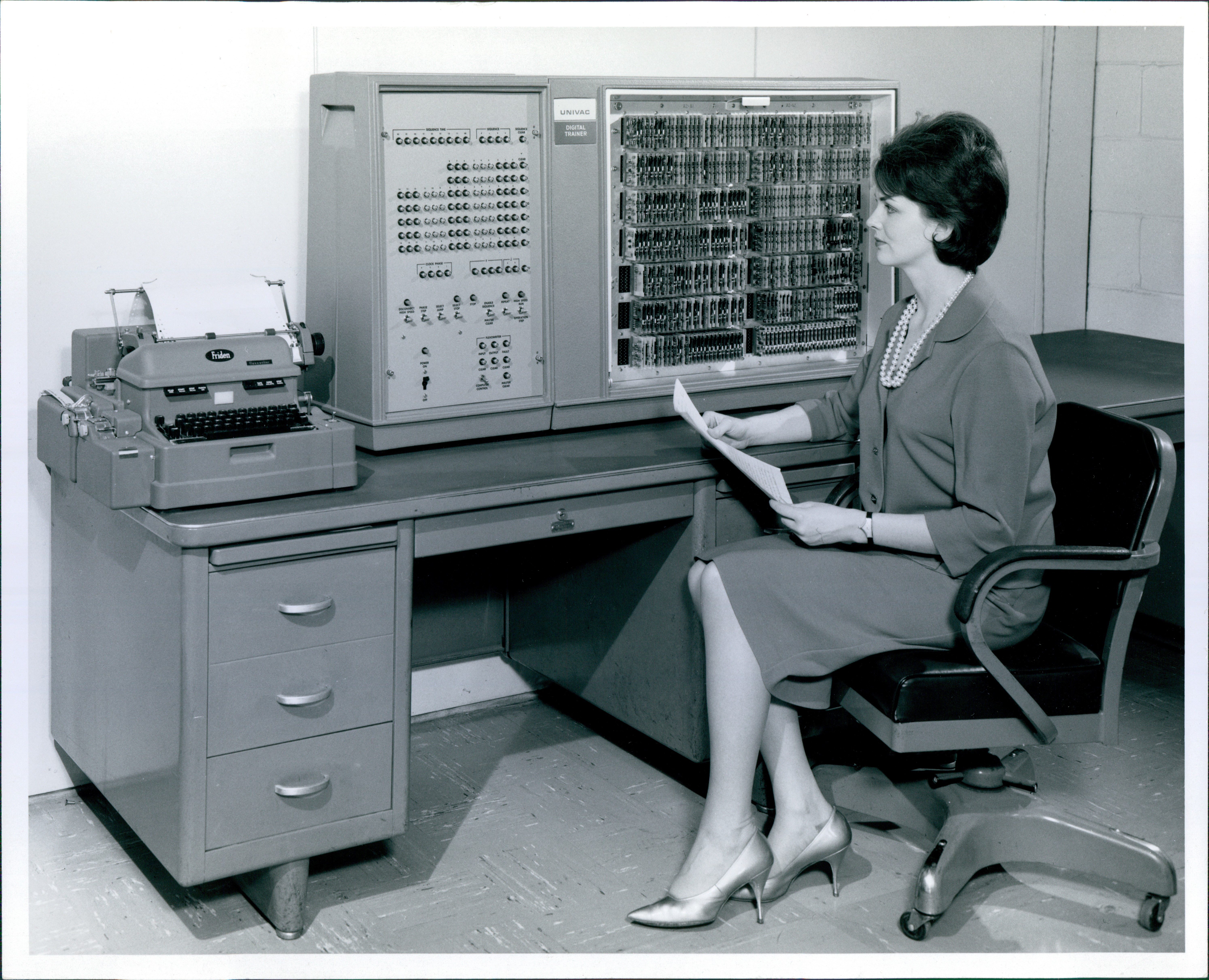
Shown at the right is a similar unit labeled UNIVAC digital Trainer. It has a Freeden Typewriter with a paper tape punch and a paper tape reader. This came from the photo collection at the Lawshe Memorial Museum, scanned by Keith Myhre.
Both of these units have a left control section and a right
Printed Circuit card array. Unlike the other image
(below) from
the Lawshe Museum that has two racks of PC cards. The
nameplate on this pictured unit says UNIVAC Digital Trainer
Unit. This looks just like the prototype that is in a scanned
sheet,
http://vipclubmn.org/Articles/UDT-6.pdf, provided by the
designer Don Mager. BTW, if you as a web chapter reader can identify
either the lady or gentleman in the snapshots, please send a note to
webmaster@vipclubmn.org
with the name, this chapter, and section number.
![]()
3.2 NIKE by Ron Schroeder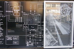
When I first went to work at Remington Rand Univac, I worked on the
Nike project. There were two computers, the TIC (Target Intercept Computer)
and MAR I (GPDC) machines built circa 1960 that were quite advanced.They
were followed by a prototype CLC machine that I believe never went into
production. Much of that work went to CDC when Joe Bloomfield [sp?] left
the company.
George Gray does provide some info in his
Sperry
Military Computers paper. John Alton's
career summary also touches
on this computer type.
 From Lowell Benson: The Nike computer system is memorialized at the
University of Minnesota along the Scholars' walk as shown in these
snapshots. Info for these two engravings came from Mr. Arndt's four
boxes of documents contributed to the Charles Babbage Institute. I had
worked with Rollie during the summer of 1963.
From Lowell Benson: The Nike computer system is memorialized at the
University of Minnesota along the Scholars' walk as shown in these
snapshots. Info for these two engravings came from Mr. Arndt's four
boxes of documents contributed to the Charles Babbage Institute. I had
worked with Rollie during the summer of 1963.
![]()
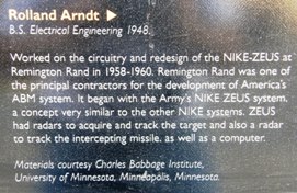
3.3 Reduced Instruction Set Computer (RISC):
 An example of specialized engineering was the
1987 RISC project. In
the mid '80s a Sperry Univac design team proposed and was awarded a
contract by the Central Intelligence Agency
(CIA) to develop a radiation-hardened MIPS RISC microprocessor chip
design. Lowell Benson was named as the Technical Program Manager. Don
Bennett was the architect for the design concept. John Porter was the
lead engineer doing the design and simulation. Dr. Vic Wells was the
Semi-Conductor facility leader for chip processing. A paper design with
a logic simulation demonstration was delivered for Phase I. RCA and Westinghouse
had a parallel phase I contracts. We and RCA were awarded Phase II contracts
to build and demonstrate chip set operation - a basic processor and
a floating point processor. Don Bennett and I presented our design at
a classified conference held on Hilton Head island off of the South
Carolina coast.
An example of specialized engineering was the
1987 RISC project. In
the mid '80s a Sperry Univac design team proposed and was awarded a
contract by the Central Intelligence Agency
(CIA) to develop a radiation-hardened MIPS RISC microprocessor chip
design. Lowell Benson was named as the Technical Program Manager. Don
Bennett was the architect for the design concept. John Porter was the
lead engineer doing the design and simulation. Dr. Vic Wells was the
Semi-Conductor facility leader for chip processing. A paper design with
a logic simulation demonstration was delivered for Phase I. RCA and Westinghouse
had a parallel phase I contracts. We and RCA were awarded Phase II contracts
to build and demonstrate chip set operation - a basic processor and
a floating point processor. Don Bennett and I presented our design at
a classified conference held on Hilton Head island off of the South
Carolina coast.
After Burroughs bought out Sperry and we became Unisys, the new management
decided to close our Eagan semi-conductor facility which was supposed
to be the builder of this Phase II radiation hardened chip set. Between
Engineering's Jim Stewart and PM's Lowell Benson, fifteen 'sand factories'
were visited to ascertain their technical capabilities. Jim and I then
prepared a Statement of Work (SOW) and Request For Quote (RFQ) documents which
were sent to six of these fifteen facilities that we had determined were
capable of building the pre-requisite 2-micron devices using our design
files. Three of the six responded to the RFQ. After using a Kepner/Tregoe
evaluation method, we selected United Technologies in Colorado Springs
to build from our design files. We then did an update to our design files
to adapt the design to their processing design rules. They built, we
demonstrated, our extensive simulation led to first pass operational
silicon chips during phase II. Great job by John Porter, I had hired
him a couple yers earlier as he graduated from the U of MN. {Editor's Note: We ended up with a few
spare parts from the assembly process. As program manager, I kept one
to use in presentations, shown at the right - now in the Lawshe
Memorial Museum.}
This was the world's first radiation hardened 32-bit microprocessor on a single chip according to our CIA sponsor!
In spite of having to change to a new manufacturing
facility, we were within budget on this Cost Plus Fixed Fee contract. We
were only a month behind the original proposed schedule. According to
our CIA technical contact, RCA was four months behind and over spent.
The CIA then opened the competition to four companies for Phase III,
production and integration. Neil
Hahn brought in a 'systems engineer' from Harris [I don't recall his
name] to lead our proposal effort. WE LOST, a minor moral victory was
that the CIA directed the winning bidder to use United Technologies
as the primary manufacturer of their chip set. [lab]
![]()
3.4 CP-2044:
The CP-2044 used three 68040 microprocessor chips to effect an emulation
of the CP-901 ISA as a next generation replacement for the core processor
in the Lockheed P-3C ASW aircraft for NAVAIR. The 1st chip fetched
an instruction from memory, the 2nd chip executed the instruction,
and the third chip took care of the Input/Output processing. [lab]
Today the P-3C’s anti-surface warfare improvement program (AIP)
mission system is used on 98% of the world’s maritime surveillance
aircraft (MSA). Since the early 1960’s we have contributed to
more than five million successful MSA flight hours.
 The Lockheed Martin Clearwater manufacturing facility donated a
CP-2044 unit to the legacy committee for display at the Lawshe
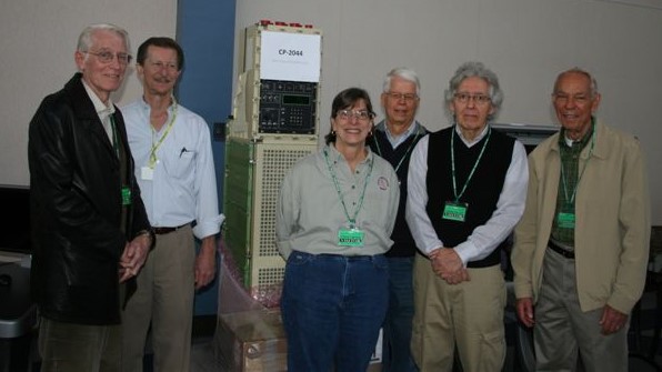
Memorial Museum in S. St. Paul. In this November 10th 2012 photo from Keith Myhre are: Gary Reetz, Chuck Hobus, CP-2044, Tricia Myhre, Les Nelson, Bob Pagac, and Art Francis.
The Lockheed Martin Clearwater manufacturing facility donated a
CP-2044 unit to the legacy committee for display at the Lawshe
Memorial Museum in S. St. Paul. In this November 10th 2012 photo from Keith Myhre are: Gary Reetz, Chuck Hobus, CP-2044, Tricia Myhre, Les Nelson, Bob Pagac, and Art Francis.
If this computer looks a bit odd, it is. Although the electronics
took up significantly less volume than CP-901, the unit was built to
fit into the same footprint the P-3C aircraft - even to the same
height so that the existing cable connections would reach (these are
the red connector covers at the top of the unit. The maintenance
panel has a rectangular digital display instead of the two 30-bit
wide LED indicators for internal register display. The screen
like front has an air filter as the rear cooling fans such air
through the unit's heat exchangers. The beige paint is the
same as used on the CP-901.
More information about the defense application is in the systems airborne chapter and the 30-bit computer chapter. [lab]
3.5 AN/USQ-69 & AN/UYQ-70:
In the late 1970’s personal computers (PC) were only just in their infancy after being conceived by many like Bill Gates and Steven Jobs. The engineers at the Naval Electronics Command (NAVELEX) came to Sperry Univac, providers of the Navy’s AN/UYK-7 standard large scale computer and AN/UYK-20 standard small scale computer to see if a personal computer could be designed and built for usage aboard the Navy’s ships and submarines. Years later laptops and Pansonics’s Toughbook© are as common as telephones, smart-phones, and tablets, but in the 1970’s, there was nothing like a PC that could survive the rigors of an at sea environment. The AN/USQ-69 was designed, developed, and produce to do just that. Although developed as a 'ruggedized personal computer', the Navy chose to assign its' nomenclature as a display - see http://vipclubmn.org/peripherals.html#Displays - section 6.3.
Q-70: In 1993 Unisys Defense Systems wrote a proposal to replace the USQ-69 with more robust processing. We were announced as the winner in 1994.
The family of ruggedized display consoles and processors comprised by the Navy’s AN/UYQ-70 Advanced Display System is the Government’s largest commercial off-the-shelf program. Q-70 has successfully harnessed the rapidly advancing computing technology of the commercial realm through its ground-breaking technology refresh process. Thousands of Q-70s populate the Navy’s subsurface, surface and airborne platforms.
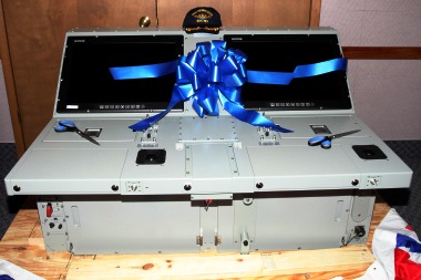 The LMCO MS2 team delivered the 8,000th AN/UYQ-70, or Q-70, combat console
suite to the U.S. Navy. A ribbon cutting ceremony to commemorate the
milestone was held at MS2’s Clearwater, Fla. facility on March
2, 2011 - attended by over 100 Q-70 program team members and Clearwater
employees. John Nikolai, Director, C4 programs for MS2 Undersea Systems,
spoke at the event and commemorated the dedication and commitment of
the team.
"For
the past three years it’s been my privilege to lead the Q-70 team
at Lockheed Martin,” Nikolai said. “You delivered to the
fleet with reliability five times the requirement and collectively you’ve
saved the Navy over $1.8 billion under the Q-70 contract. The team delivers
what it promises.
The LMCO MS2 team delivered the 8,000th AN/UYQ-70, or Q-70, combat console
suite to the U.S. Navy. A ribbon cutting ceremony to commemorate the
milestone was held at MS2’s Clearwater, Fla. facility on March
2, 2011 - attended by over 100 Q-70 program team members and Clearwater
employees. John Nikolai, Director, C4 programs for MS2 Undersea Systems,
spoke at the event and commemorated the dedication and commitment of
the team.
"For
the past three years it’s been my privilege to lead the Q-70 team
at Lockheed Martin,” Nikolai said. “You delivered to the
fleet with reliability five times the requirement and collectively you’ve
saved the Navy over $1.8 billion under the Q-70 contract. The team delivers
what it promises.
 Ceremony attendees also heard from Robert Jackson, Deputy Program Manager
for the U.S. Navy’s Submarine Combat System Program Office (PMS-425).
Jackson spoke about the value the program has brought to the Navy, saying “The
one thing that never comes up is reliability problems with this product.
That’s something everyone needs to be proud of…because it’s
appreciated. [The Navy] is taking your product into environments that
are harsh…and the product stands up, day in and day out.”
Ceremony attendees also heard from Robert Jackson, Deputy Program Manager
for the U.S. Navy’s Submarine Combat System Program Office (PMS-425).
Jackson spoke about the value the program has brought to the Navy, saying “The
one thing that never comes up is reliability problems with this product.
That’s something everyone needs to be proud of…because it’s
appreciated. [The Navy] is taking your product into environments that
are harsh…and the product stands up, day in and day out.”
MS2 [UNISYS/Loral/Lockheed Martin] has been the lead contractor on
the Q-70 program since it was first awarded in 1994. Components of the
system can be found on surface warships, aircraft and shore stations
around the United States. Q-70’s have also benefited other internal
MS2 products over the past decade, such as the Aegis combat system found
on Ticonderoga-class cruisers and Arleigh Burke-class destroyers and
the E-2C Hawkeye Airborne Early Warning (AEW) aircraft.
The Q70’s have been primarily built by our teammate/subcontractor
DRS Technologies in Johnstown, PA [former congressman Jack Murtha’s
district] along with a subset of units being built in Clearwater. Clearwater
is now building about 40% of the units. The program is approaching $3B
over its life – not bad for a projected loss leader that no one
really wanted in the 1990’s
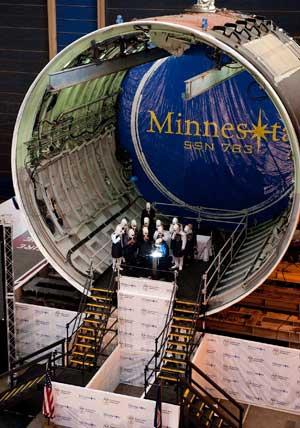
This unit was installed in the USS Minnesota, SSN 783. This submarine naming ceremony is illustrated at the right, photos in this section are from an LMCO news release. John Westergren
3.6 T3097 - Portable (suitcase) Computer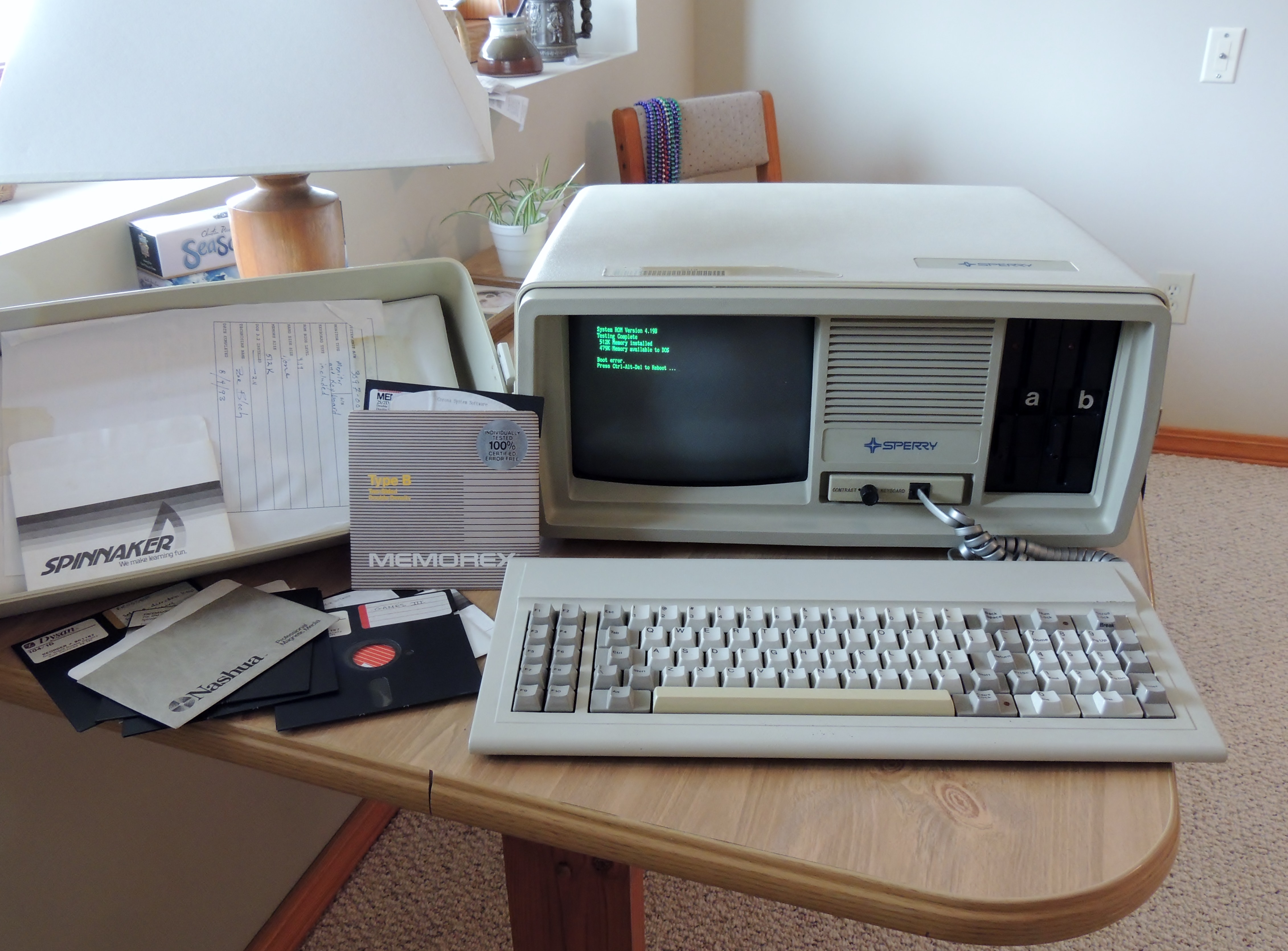
This Sperry developed unit had the keyboard stored in the suitcase cover for transporting, it weighed about 35 pounds. The BIOS was set to bootstrap from the A drive, a 5.25" floppy disc drive. It was used for the CORONA system according to page 432 of GS3577. The Legacy Committee has two of these units at the Lawshe Memorial Museum.
08-84, PORTABLE PERSONAL MODEL SP1, 60HZ 120V MICROPROCESSOR-BASED PERSONAL COMPUTER DESIGNED TO BE USED ON A DESK OR COUNTER WITH PROVISIONS MADE FOR ALLOWING TRANSPORTABILITY. CONSISTS OF 8088 MICROPROCESSOR. 256K BYTES OF MEMORY. FLEXIBLE DISK CONTROLLER~ ONE 5 1/4 INCH 360K BYTE DISKETTE. MONOCHROME/COLOR ADAPTER BOARD. 9 INCH VIDEO DISPLAY. ONE SERIAL. INTERFACE. ONE PARALLEL IlNTERFACE. KEYBOARD CHARACTER SET ROM. POWER CORD, FOUR EXPANSION SLOTS, MS-DOS. GW BASIC. AND DIAGNOSTIC DISKETTE. 60HZ 120V.
R50305 R-R 08-84 PORTABLE PERSONAL COMPUTER MODEL SP2. 60HZ, 120V SAME AS MOnEL SPI (3091-00) EXCEPT INCLUDES TWO 5 1/4 INCH DISKETTES ~ 60HZ, lZ0V.
R50305 R-R 08-84 POtHAne PERSONAL COMPUTER MODEL SPx. 60HZ, 120V SAME AS MODEL SP1 (3097-00) EXCEPT INCLUDES ONE 5 1/4 INCH DISKETTE AND ONE 10M BYTE FIXED DISK DRIVE AND CONTROLLER. (THE FIXED DISK CONTROLLER USES ONE EXPANSION SLOT.
3.7 Central Logic and Control (CLC) module
Dear Sir, I was doing research on the computer system at the Cavalier
Air Force Station (CAFS) and came upon your web site. The computer at
Cavalier Air Force Station (AFS) is a Univac CLC model 2.
See right column, page 4 of Univac_Third_Generation computers.
The CLC computer is still in operation at the PARCS radar system, located
at CAFS, North Dakota. It was designed in the mid-60's and was built
somewhere between 1969-1973. It has been (and still is) in continuous
operation (24/7) since 1973. The Cavalier Air Force Station was part
of the ABM system that was built in the 1969-1973 time-frame.
As you are probably already aware, the CLC model 2 is a multi-processor
computer that is expandable up to 10 PUs (fifteen (15) according to
other reference material I have read), 16VS, 16PS, 2T&S, and up
to 2IOCs (up to 4 depending upon which reference material you read.)
The memory is all core-memory with water cooling used on all racks,
and water and air for the core memory units. The hardware is software
partition able to allow the formation of two separate computers of varying
sizes dependant upon software requirements, and available hardware.
The CLC in operation at Cavalier Air Force station has a configuration
of 7 processor units (or PUs), and two (2) Input/Output controllers
(IOCs). The memory is core-memory, with 16 variable stores and 10 program
stores.
There was a 10PU, 16PS, 16VS, 2IOC, 2T&S CLC model 2 configuration
at the MSR system located at Langdon ND. This system was shutdown and
dismantled as a result of the SALT treaty in about 1976-1977 time frame.
The MSR CLC was also dismantled and some of the parts delivered to PARCS
in 1977-1978, with the remaining CLC pieces being sent to DRMO and scrapped.
There was also a CLC model 2 with a 1PU, 3VS, & 3PS.
from Ronald Belanus - June 2, 2009
![]()
4.0 Special Purpose Computers
June 2008 - Recollections from 40+ Years Ago - John Alton [with help]
4.1. Introduction
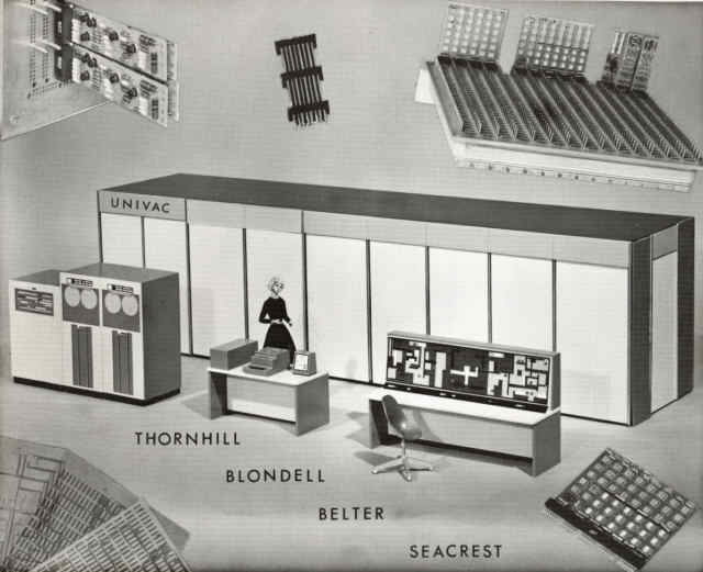
Following is an unclassified summary of special purpose computers
built under US Navy contract by Sperry Univac during the period from
the mid 1950s through 1967. These computers in development sequence
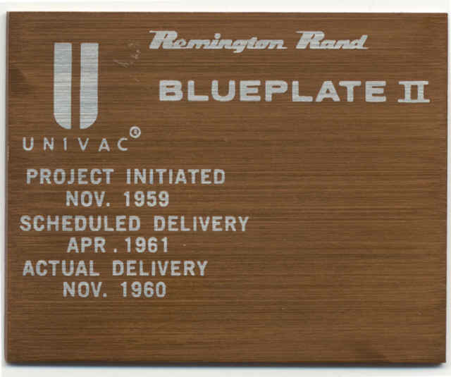
were called: Blueplate I, Blueplate II, Thornhill, Blondell, Belter
I, Belter II, and Seacrest.
The application of these machines involved solving very large computing
problems. This was accomplished by using an exceptionally large quantity
of logic and memory circuits and by implementing most of what would
normally be done by software with hardware circuits instead. These machines
had roughly ten times the number of logic circuits as our general purpose
machines at the time.
The following descriptions focus primarily on Thornhill because it was
the first in the series that used new technology followed by other machines
which used essentially the same basic technology.
Thornhill Cabinet Structure
a) General
 The
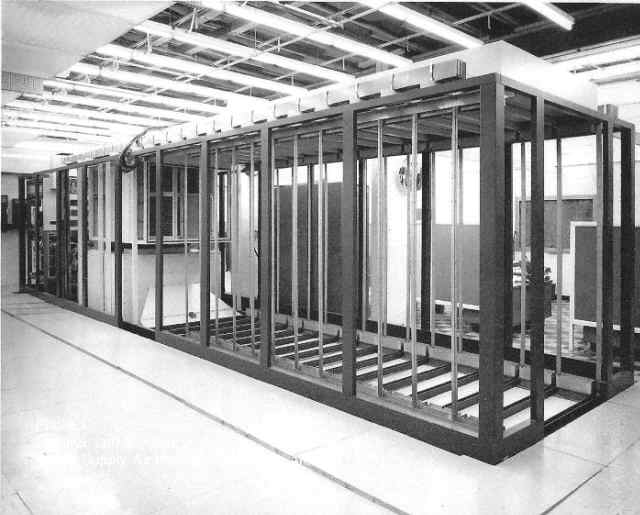
Thornhill machine was housed in a large cabinet 35 ft long X 8 ft high
and 7 ½ ft. wide. The cabinet contained three major sections, the electronics,
the air handler portion of the cooling system, and the power supplies.
Photo 1 [right] shows the cabinet under construction. On the left are
the power supplies. In the center is the air handler portion of the
cooling system. On the right is the electronics end of the cabinet.
The
Thornhill machine was housed in a large cabinet 35 ft long X 8 ft high
and 7 ½ ft. wide. The cabinet contained three major sections, the electronics,
the air handler portion of the cooling system, and the power supplies.
Photo 1 [right] shows the cabinet under construction. On the left are
the power supplies. In the center is the air handler portion of the
cooling system. On the right is the electronics end of the cabinet.
b) Electronics
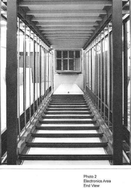
- The electronics end of the cabinet has two banks for electronics
with a walkway between them for access to the back side of the chassis.
Photo 2 [below left] shows an end view where the chassis will be
installed. There are five bays on one side and 4 bays on the other.
Each bay contains 15 chassis; 3 wide and 5 high for a total of 135
chassis.
- The chassis were made up of a stack of alternating printed circuit
back panels and insulating layers topped by a ¼ inch thick aluminum
ground plate. The back panels were made up of many [up to 20] 15”
X 12” two layer printed circuit boards with plated through
holes. The back panel boards and the ground plate were interconnected
with electro-less nickel and gold plated roll pins that also formed
part of the sockets which accepted the logic and memory circuit
cards.
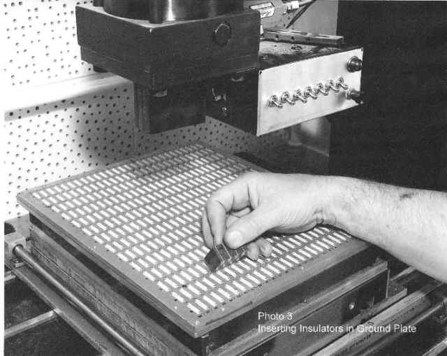 Photo
3 [below right]shows the ground plate with white plastic insulators
that were molded into the ground plate. It shows ground bushings
being inserted into the ground plate to connect the circuit cards
to the ground plate, two bushings per connector area. The roll pins
that interconnect the back panel boards will terminate at the surface
of the white insulators, forming the socket for the circuit cards.
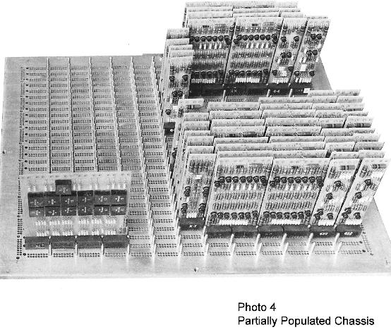
The circuit cards, which were made with discreet components, were
unique in that the connector pins were not straight, but waved such
that there were multiple opposed pressure points where they mated
with the back panel roll pins. This provided a highly reliable connection.
Single width cards were 1” wide X 4” high. Cards were
also made in multiple widths. Photo 4 [below left] shows a partially
populated chassis.
Photo
3 [below right]shows the ground plate with white plastic insulators
that were molded into the ground plate. It shows ground bushings
being inserted into the ground plate to connect the circuit cards
to the ground plate, two bushings per connector area. The roll pins
that interconnect the back panel boards will terminate at the surface
of the white insulators, forming the socket for the circuit cards.
The circuit cards, which were made with discreet components, were
unique in that the connector pins were not straight, but waved such
that there were multiple opposed pressure points where they mated
with the back panel roll pins. This provided a highly reliable connection.
Single width cards were 1” wide X 4” high. Cards were
also made in multiple widths. Photo 4 [below left] shows a partially
populated chassis. -
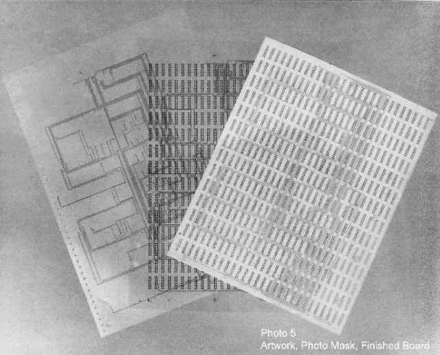
 Printed
circuit routing for back panel artwork was generated by automated
design programs developed for the project. These programs also drove
a large flat-bed plotter which rendered the artwork used for fabrication.
Photo 5 [below right] shows artwork, photo mask for etching, and
a finished back panel board.
Printed
circuit routing for back panel artwork was generated by automated
design programs developed for the project. These programs also drove
a large flat-bed plotter which rendered the artwork used for fabrication.
Photo 5 [below right] shows artwork, photo mask for etching, and
a finished back panel board.
- Clocking the Thornhill circuits at 10 MHz was a major challenge. It was solved by synchronizing the clock with fine tuning the timing circuits to nanosecond accuracy at each of the 135 chassis in the machine.
c) Power Supply and Distribution
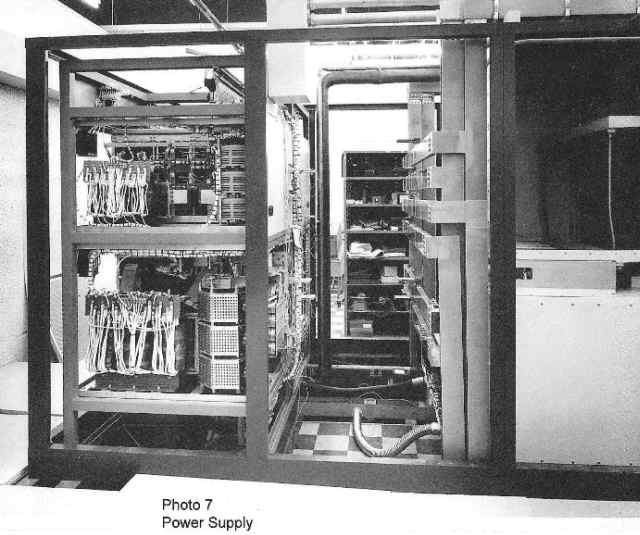
- The two large power supply cabinets and power supplies were developed by the Bogue Electric Corp under contract from the Thornhill project. Five voltages were provided; among them +5V, +15V, and a negative 5V. Two thousand amps were delivered by the +5V supply. Lesser current was delivered by the other power supplies.
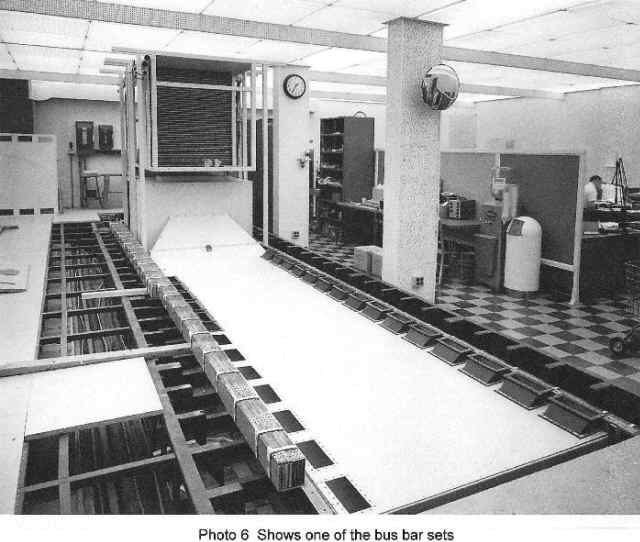
- The power was distributed to the chassis by a series of bus
bars. The main bus bars traversed horizontally along the cabinet
bottom and top of each side of the cabinet from the power supply
to every bay of chassis. Photo 6 [below left] shows one of the four
bus bar sets.
 Smaller
vertical bus bars carried power to the chassis stacked 5 high and
3 wide in each bay. The main busses were made up of 2 copper bars,
each ½ inch thick and 4 inches high, separated by a very thin dielectric.
This design was chosen to maximize the capacitance and minimize
the bus inductance.
Smaller
vertical bus bars carried power to the chassis stacked 5 high and
3 wide in each bay. The main busses were made up of 2 copper bars,
each ½ inch thick and 4 inches high, separated by a very thin dielectric.
This design was chosen to maximize the capacitance and minimize
the bus inductance. - Photo 7 [below right] shows (between the power supplies and
the air handler) the bus bar terminations that will eventually be
connected to the power supply.
- A 150 horsepower motor-generator set provided ac power to the power supplies.
d) Cooling system
- The cooling system provided 35 tons of air conditioning, built as a conventional refrigerant evaporator – condensing unit system with an added 100 Kw reheat unit. This allowed the air to be cooled below system requirements to dry the air by condensation then reheated to the correct cooling temperature for the electronics.
- The evaporator unit is housed in the air handler shown on photo 1. The air handler is driven by a 20 horsepower blower. The compressor and make-up water tank are located elsewhere and are shown in photo 8. [below]
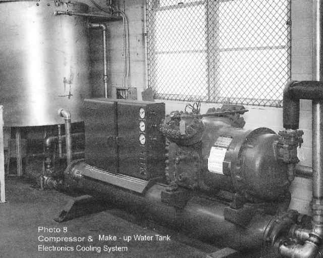
The condensing coil was in the cooling tower located on the roof of the building.
• Photo 6 also shows plenum air outlets for each column of chassis on one side of the cabinet. Return air would be captured by similar boots above each column of chassis. The same design applies to the other side of the cabinet.
4.3 Blondell
The same technology was used on Blondell as was used on Thornhill.
4.4 Belters I and II Cabinet Structure
a) General
The Belter cabinets; housing the electronics, air handler and power
supplies were 32 ft long, 8 ft high and 7 ½ ft wide, three feet shorter
then the Thornhill. The system also included a 1230 Computer, 1532 I/O
Console, 1240 [2 handler] Magnetic Tape Unit, and our Emergency Control
Unit for switching the two Belter machines.
b) Electronics
The logic and memory circuits were packaged as in Thornhill, using many
of the same card types. The memory circuits were done with integrated
circuits.
4.5. Other Data
a) Circuits and Packaging
| Machine | Logic | Memory | Packaging |
| Blueplate I | Transfer Circuits [like USQ-17] | Magnetic Core | USQ-17 [Note 1] |
| Blueplate II | Transfer Circuits [like USQ-17] | Magnetic Core | AN/USQ-17 [Note 1] |
| Thornhill | Transistor-Transistor Logic (TTL) | Magnetic
Core Thin Film NDRO Thin Film DRO |
Described in par 4.2 b), bullet 2 above |
| Blondell | As in Thornhill | As in Thornhill except no NDRO | Ditto |
| Belter | As in Thornhill | Integrated Circuits | Ditto |
| Seacrest | As in Thornhill | Integrated Circuits | Ditto |
Note 1: Discrete component PC cards and wire wrap back panels were used on the Blueplate machines.
b) Miscellaneous
| Machine | Input Data Means | Design Area | Build Area |
| Blueplate I | Punched Paper Tape | Building 3 Basement | Plant 3 |
| Blueplate II | Punched Paper Tape | Building 3 Basement |
Plant 3 |
| Thornhill | Punched Paper Tape | Building 6* |
Building 6 |
| Blondell | 1230 Computer | Building 6 |
Building 6 |
| Belter | 1230 Computer | Building 6 |
Building 6 |
| Seacrest | 1230 Computer | Building 6 | Building 6 |
*Building 6 was located just east of the main Plant 2 office
building on Minnehaha Ave. in St. Paul. This building had an extra
fence surrounding it to provide extra security for the area.
There is more about the Building 3 Basement and Building 6 in Our
Stories #190, February: As the Sperry/Navy use of Plant 2 faded away in the
early 80s, a new tenant phased
into parts of the area.
[lab]
4.6. People Consulted
Curt Bute, Joe Kimlinger, Gordon LaValley [Provided significant data
on hardware design], Wayne Olson, Jack Pollack [Provided significant
data on Belter and Seacrest], and Norm Petrowski.
![]()
5. Special Purpose by Wayne Olson
 I came across these items while moving and reorganizing some files.
I also found my unclassified log books from 1961 to about 1965 covering
a lot of Thornhill design issues. However there seems to be a big gap
after that. I think I probably only used company logs which I had to
return when I retired.
I came across these items while moving and reorganizing some files.
I also found my unclassified log books from 1961 to about 1965 covering
a lot of Thornhill design issues. However there seems to be a big gap
after that. I think I probably only used company logs which I had to
return when I retired.
When I have time I will try to condense what I can learn from the
log books.
Included are most of the other names working on Thornhill. I have some
information on the various memories in Thornhill, both DRO & NDRO
plated wire I believe. We had a memory test setup. Flippo is mentioned
and I don't remember what that is. I also have lists of card types and
possibly some schematics.
I
 did not see anything about Seacrest, Belter & Blondell. So
that is still lost in the fog of my memory. If you have any info to
jog my memory, I would appreciate seeing it.
did not see anything about Seacrest, Belter & Blondell. So
that is still lost in the fog of my memory. If you have any info to
jog my memory, I would appreciate seeing it.
I don't remember much about Blueplate II. I think it had U-shaped
frame with a pull-out power supply to get access to the inside with
a fold-down landing gear to support it's weight. It was classified:
but I really don't remember much anyway. It was designed while Special
Applications was in the Navy Basement at Plant 2.
[By the way, I found
a picture of Plant 2.] Carl Koehler was lead logic designer. He worked
his way up from being a technician with no formal education. He was
legendary for his neat logic drawings done in No. 2 pencil. He always
had a sharp one over his ear.
His brother Howard was part of the Thornhill logic design team of
about 5 people including myself. Wayne Olson
![]()
6.0 MOD 0
bby Lyle Franklin
Lowell: I went to work at Univac in July 1956 during the beginning of a massive hiring for Mod 0. As Dick Roessler was not ready to begin the Mod 0 training class, I was assigned to the test stand in Plant 3. I reported to the test stand and worked for Bob Groeshen's crew. At that time we had orders for over 158 units. I do not know whether down payments were required. We could get the units running by inserting capacitors in the rats nest point to point wiring of the back bays. If they were detected the unit did not meet print so they were rejected and reworked until the print was changed or we hid the capacitors but included our changes in the drawings that went with the machines.
In the interim IBM worked with their customers to modify their facilities and did the debugging and final testing on customer site. Their "stick" was the machines were rental and the only cost to the customer commenced after acceptance at the facility. As computers were very new customers such as 3M waited years before the installation of their machine and longer until debug and final acceptance. IBM had the money to wait but their customer base was held captive as the market was using other IBM equipment in the interim. Remember before unbundling IBM with the better electric typewriter and could hold their customer base. On the other hand we needed the revenue but our long association with the government had influenced our methodology of billing after final delivery and final testing to print.
When Jimmy Rand sold Remington Rand to Sperry they expected a large influx of cash to save them but really received a cash eater. Sperry was on a going out of business curve and Gyro had decreased from 25,000 to under 5,000. Univac was using up funding that Sperry wanted for Gyro product development. The other Sperry equipments were analog. Big problem with our relationship with Gyro and Ford Instrument Company, the producer of the standard Navy fire control computer. Any funding we received was grudgingly given.
Hope this gives you another viewpoint - Lyle
In this Chapter
- Introduction [left]
- 1624
- Computer Types: UDT | NIKE | RISC | CP-2044 | USQ-69 and UYQ-70 | T3097 | CLC
- Special Purpose by John Alton
- Special Purpose notes by Wayne Olson
- MOD 0 by Lyle Franklin
Chapter 58 edited
7/13/2025
![]() |
Home, Pg 1 |
Our Legacy, Ch 1 |
People |
Locations |
Engineered |
Computers |
Systems |
Contacts and Links |
Site Map, Pg 0 |
|
Home, Pg 1 |
Our Legacy, Ch 1 |
People |
Locations |
Engineered |
Computers |
Systems |
Contacts and Links |
Site Map, Pg 0 |
Copyright ©2025, LABenson for the VIP Club. All Rights Reserved; Hosted on www.webhostinghub.com since 2011.