

Information Technology (IT) Pioneers
Retirees and former employees of Unisys, Lockheed Martin, and their heritage companies
Air Force Computers, Chapter 57
This US Air Force computers chapter reflects the few airborne computer units developed by
UNIVAC/Sperry/Unisys in the
Twin Cities.
There were a few hardware pluggable modules that were common across
architectures leading to simplified support logistics. One of these were the Reconfigurable Module Family (RMF) that
started the use of purchased memory modules instead of in-house designed and manufactured.
The RMF modules were 6" x 9" and fit a full Alex Trumble
Relay (ATR) rack mount chassis.
The 'Minuteman' Computers developed for the Air Force missile launching systems are discussed on the Computers, 18-bit chapter.
2.0 Genealogy Chart for Air Force Computers.
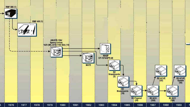
At the right is a section of the UNIVAC/UNISYS/LMCO genealogy chart that were computers developed under Air Force contracts after Internal Research and Development projects put together the Reconfigurable Module Family 500 (RMF) unit to demonstrate execution of the AF's Mil-Std-1750A repertoire Instruction Set Architecture.
3. Computer Types
3.1 2052 - The world's first digital airborne computer
This computer doesn't appear on the AF computer genealogy above because when this chart was made we weren't aware of the earlier unit. When writing a career summary for the Legacy project in 2012, Dr. George Champine identified his first project as the 2052 - the world's first digital airborne computer developed then tested aboard a B-24.
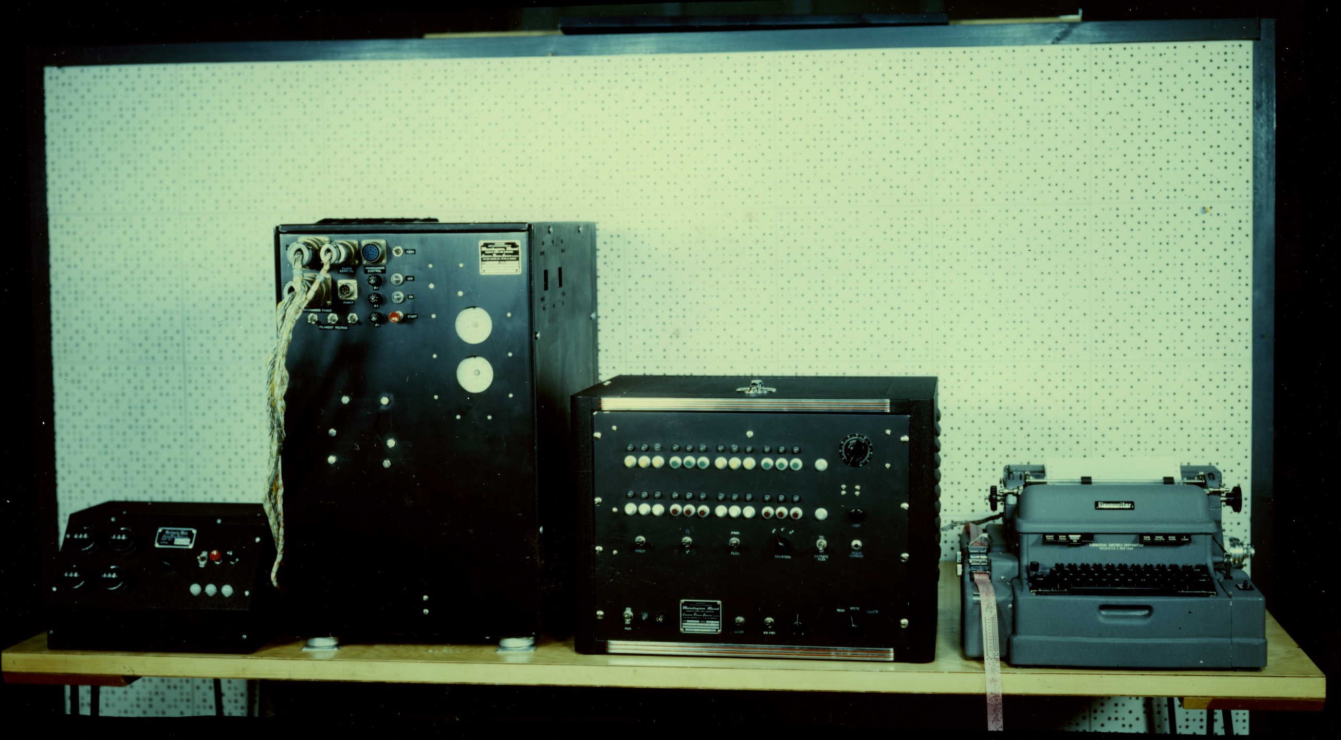 Note: The picture shown {at the
left} for the Airborne Computer includes a tester, equipment for initial programming, and a Flexowriter;
but only the single unit containing the computer and conversion equipment is
necessary or is used after the initial program is read into the computer's memory." These
three photos are from the collection at the Lawshe Memorial
Museum, thanks Keith Myhre.
Note: The picture shown {at the
left} for the Airborne Computer includes a tester, equipment for initial programming, and a Flexowriter;
but only the single unit containing the computer and conversion equipment is
necessary or is used after the initial program is read into the computer's memory." These
three photos are from the collection at the Lawshe Memorial
Museum, thanks Keith Myhre.
I, Lowell Benson, have correlated
Dr. Champine's career summary description with an entry in the 1947-59 UNIVAC
products book - text hereunder. If one takes a look at the on the
24-bit
computer chapter genealogy chart , on the lower left a reader would see the
Airborne Scaling computer, that photo looks just like the
unit adjacent to the Flexowriter on the right of this photo.
"The Airborne Computer, developed under the name of Scaling-Multiplier Incremental computer, is a special-purpose machine
developed for the United States Air Force.
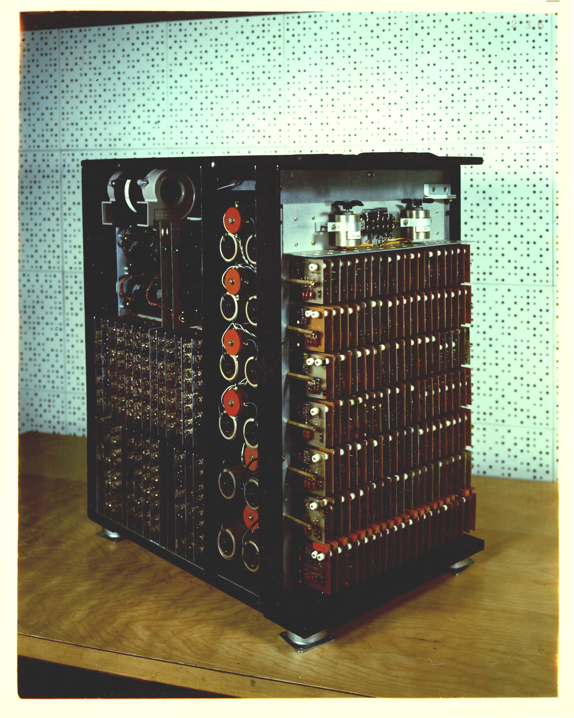 The Central Computer is based on a novel technique, developed by Remington Rand Univac St. Paul engineers. This invention relates
to an incremental method of computation that is especially suited to control system applications where inputs vary in a continuous manner.
By this method, the results of previous solution are used in order to arrive at a new solution. This logic makes possible a desired reduction in components
compared with those necessary in conventional general-purpose systems
The Central Computer is based on a novel technique, developed by Remington Rand Univac St. Paul engineers. This invention relates
to an incremental method of computation that is especially suited to control system applications where inputs vary in a continuous manner.
By this method, the results of previous solution are used in order to arrive at a new solution. This logic makes possible a desired reduction in components
compared with those necessary in conventional general-purpose systems
An Analog-to-digital and digital-to-analog converter is included in the machine, based on magnetic techniques.
Fifteen channels are available for input-output; word length may be variable, although a 20-bit length is used for the majority
of operations. The speed of the system in operation is high, with a sampling rate of 200 times per second; this is to say
that all inputs will be sampled, new computations performed; and corrected output provided at the rate of 200 times per second."
{Editor's note: in polar coordinate mathematics' systems, 20
bits can contain angle values of degrees, minutes, and
seconds.}
"Description: A single unit, four cubic feet in size, contains the power supply, the Central Computer including magnetic drum and
ferrite core storage, and the analog-to-digital and digital-t0-analog converter equipment.
The machine is well suited,
therefore, to airplane control system applications in which the size of airborne equipment must be as small as possible.
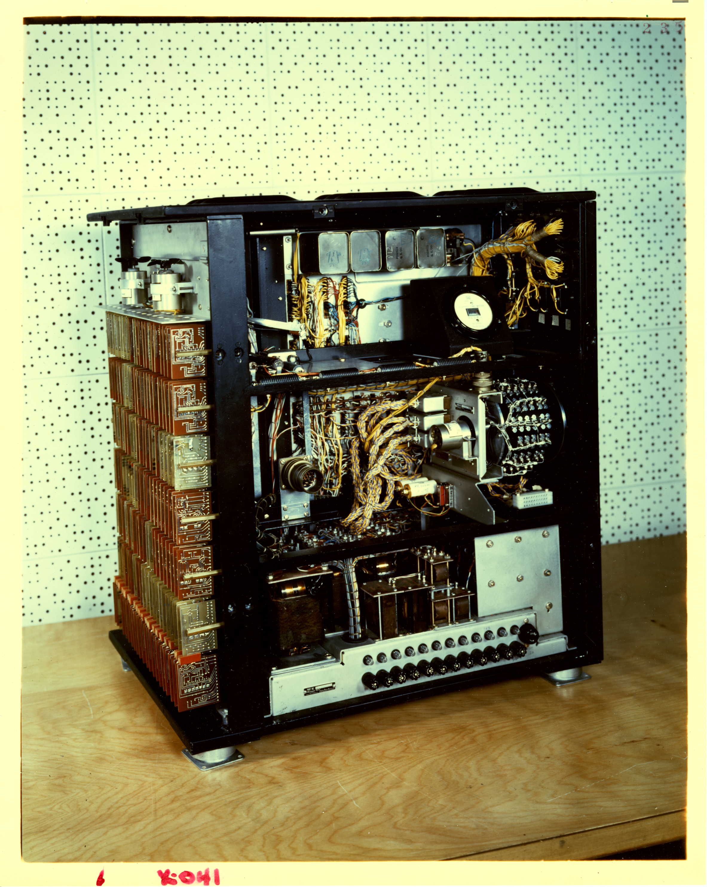 A nonvolatile type of program storage is used so that power may be turned off at any time, and when turned on again, the
operation starts without necessary reprogramming.
A nonvolatile type of program storage is used so that power may be turned off at any time, and when turned on again, the
operation starts without necessary reprogramming.
The heart of the analogue-to-digital and digital-to-analog conversion equipment is a group of magnetic cores that use
moly-permaloy material. This results in an accurate, speedy conversion, and extremely rugged hardware that is not affected
either by the movements of the plane or by temperature changes.
Note: The picture shown {at the left} for the Airborne Computer includes a tester, equipment for initial programming, and a Flexowriter;
but only the single unit containing the computer and conversion equipment is
necessary or is used after the initial program is read into the computer's memory."
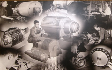
The circa 1953 drum photo collage at the right has a small drum in hands of engineer Don Weidenbach. Toward the bottom right we see two hands installing a read or write head into a small drum memory. If we look at the photo in section 2.1 of http://vipclubmn.org/Memory.html, we also see a miniature drum memory in Don Weidenbach's hands. These photos from the early 50s show that a small drum memory technology was already available in 1956 when the 2052 computer development took place. [LABenson]
Remington Rand Document PX-56-4 copied from the Bitsavers' website has a description and programming guide.
3.1 RMF 400
Not obvious on the Genealogy chart below was that the RMF-400 was built as an emulator of the Singer Kerrfot 2070 computer which was originally used aboard the B-1 bomber. [lab]
I was the Northwest marketing rep at the time of the Singer Kearfott emulator. It was initially bid to Boeing Seattle for the original B-1 Program. Boeing felt Singer Kearfott was overcharging them. When Gene Weller, Headquarters Marketing, and I reviewed the requirement with Glen Kregness, Glen's analysis was we needed a board to replicate some of the functions we couldn't address with the MPC technology. Thus was born the "computer adapter board, the efficient method for hardware replication." Boeing engineers loved it and we did win the competitive procurement. Unfortunately the original B-1 program was cancelled and we were not the winner when it was reactivated. [Lyle Franklin]
3.2 WASP
The Weasel Attack Signal Processor (WASP) was used aboard the F-4G Phantom II airplane. This machine executed the AF MIL-STD-1750 Instruction Set Architecture commands. It was connected to sensors for the AN/ALQ-119 electronic countermeasures mission plus lauch software for Shrike and Maverick missiles. [lab, info from internet.]
3.3 B-2
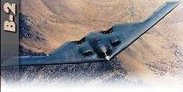 Another version of the RMF family is aboard the B-2 stealth bomber. This was a classified development until the
rollout of the first airplane. Jim Inda was the Project
Engineer responsible for development of the computer(s) for
this airplane. Jim's story is our
January 2015 Article. {Editor's note: Photo found on the internet.}[lab]
Another version of the RMF family is aboard the B-2 stealth bomber. This was a classified development until the
rollout of the first airplane. Jim Inda was the Project
Engineer responsible for development of the computer(s) for
this airplane. Jim's story is our
January 2015 Article. {Editor's note: Photo found on the internet.}[lab]
![]()
3.4 YF-23
 The AN/AYK-15A computer implemented the Air Force Mil-Std-1750A Instruction Set Architecture. The AF
defined the 1750 ISA in order to bring standards to their system support chaos which had over 300 ISAs in equipments
from thirty some vendors Several variations of this ISA were designed over time. A notable variation was the
"Common Module Family" that was built for Northrop for their YF-23.
The AN/AYK-15A computer implemented the Air Force Mil-Std-1750A Instruction Set Architecture. The AF
defined the 1750 ISA in order to bring standards to their system support chaos which had over 300 ISAs in equipments
from thirty some vendors Several variations of this ISA were designed over time. A notable variation was the
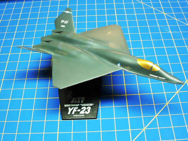
"Common Module Family" that was built for Northrop for their YF-23.
The Department of Defense chose the Lockheed
YF-22 as the Advanced Tactical fighter after a fly-off. Model shown at the right from Lowell's memorabilia collection.
[lab]
3.5 Joint Strike Fighter (JSF): by Dick Erdrich
The Integrated Core Processor (ICP) subsystem
provides critical processing capabilities for the aircraft’s
sensors, communications, electronic warfare guidance and
control and cockpit displays.
I was involved with the original
engineering effort for the F-35 [Joint Strike Fighter]
program. We had used an existing processor module from
the Owego Division [Old IBM Federal Systems Division] and I
had been tasked with the overall processor design which used
the module and, after the initial deliveries for software
development had been made, was asked to study the possibility
of increasing the number of processors on each module for the
production program. I did my study and to my surprise
management gave the go ahead to build it. It was done on
IR&D money so outside interference was not an issue.
After an 8 month effort, done mostly as I would have in the
old days, the Quad Processor was operational. I used two
Freescale [Motorola] processors per module side of an 6" x 9"
Printed Wiring Board (PWB) - with all of the usual support
hardware - three types of memory, UARTs, E-Nets etc.
With all of the decoupling capacitors and transmission line
terminators necessary for the high speed stuff I ended up with
over 2100 components on the PWB. Two PWB's would
be bonded together to make up the module. It was
operational the first time around, no artwork changes were
necessary. We again let the software development folks
use the initial hardware but I got a chance to do it again as
now the customer got involved and wanted the very latest
processor available for production. I spent a
solid month doing the design for the upcoming processor chip
and then turned it over to Dave Senechal, Reed Churchward,
Charles Grimmner, and Don Degerstrom. They are going
through the normal problems of trying to get leading edge
components but they will be successful.
After 47 years, 4 months, and 13
days I didn't feel as though I needed to hang around just to
watch another processor run. Its' been a heck of a
run! Dick
![]() |
Home, Pg 1 |
Our Legacy, Ch 1 |
People |
Locations |
Engineered |
Computers |
Systems |
Contacts and Links |
Site Map, Pg 0 |
|
Home, Pg 1 |
Our Legacy, Ch 1 |
People |
Locations |
Engineered |
Computers |
Systems |
Contacts and Links |
Site Map, Pg 0 |
Copyright ©2025, LABenson for the VIP Club. All Rights Reserved; Hosted on www.webhostinghub.com since 2011.