

Information Technology (IT) Pioneers
Retirees and former employees of Unisys, Lockheed Martin, and their heritage companies
Chapter 44, Interface Engineering
1. Introduction.
As systems evolved, there was always a need for electronics and/or special equipment to interface with computers.
The greatest need was for communications between devices within systems and between multiple systems. Our engineers helped set the standards for the defense industry in many key areas. Today's most common interface use is the internet, the history is documented in many places thus we do not try to summarize that history hereunder. The UNIVAC/UNISYS perspective of networking is related in a John Nemanich article.
Thanks to Marc Shoquist, Dick Erdrich, and others for their contributions to this page.
2. Point to point by Lowell Benson, U of MN - BEE 1966
The first Naval Tactical Data Systems interface was a 30-bit wide parallel communications path using data and control level signals of 0 volts and -15 volts. The computer program would open up either an output or an input buffer. When a peripheral device was ready to accept a word, it would turn on an output data request line. The computer would accept the output request, enter data into an output holding register, four microseconds later an 8 microsecond output acknowledge signal line was activated. The holding register information was held for another 3 microseconds - meaning that it took a total of 15 microseconds to transfer a word. The peripheral would drop its request line, then turn the line back on when it was ready for another word. If it was input to the computer, the peripheral would load a register, then activate the input request line. The computer would sample the data lines then send an 8 microsecond acknowledge pulse. The peripheral would then drop the request line, reload its register with the next word (or byte), and repeat the process. A similar method was/is used for control signals to the peripheral and status information back from the peripheral. This request/acknowledge process allowed reliable point to point communications up to 300 feet - a communication rate of 45,000 words per second. Obviously printers weren't this fast but inter-computer communications were. ERA documented this communications method into Design Specification DS-4772. This Design Standard was the basis for MIL-STD-1397 that evolved to encompass both parallel and serial computer and peripheral interfaces.
{Editor's note: I recall Ernie Lantto relating that a JPL
installation had had one communication link operating over several
miles using this '-15 volt' method - from a top of a local mountain
to their facility at the base of the mountain.}
As Germanium transistor use became prevalent instead of vacuum tubes,
research found that using a -3 volt signal swing could reliably communicate
over 200 feet at a faster rate. The register loading had a 2 microsecond
advance time followed by a four microsecond acknowledge pulse. This
went into DS-4772.
Silicon transistors brought a new era to this interface
method. The signal swings could be 0 volts to +4 volts [or so.] DS-4772
was updated, now labeling these three interfaces as Type A, Type B,
and Type C. The Type C became the interface of choice for the airborne
1830 using a 2.5 microsecond acknowledge. This provided a data transfer
rate of up to 167,000 words per second, i.e. a word every 6 microseconds.
This was nicknamed the ANEW interface (yes that means 'a new' interface
- ANEW is not an acronym!) I believe that Ernie Lantto was the engineer
responsible for the accuracy of these revisions to DS-4772.
The Navy Laboratories doing research had UNIVAC experiment
with point to point serial interfaces using co-axial cable. This led
to the Type D interface in DS-4772. A Type D interface was designed
for the AN/UYK-7 computer, Ken Graber was one of the engineers. The Navy
then transitioned the UNIVAC specification into a Navy standard, Mil-Std-1397,
so that it would 'have control' over their interfaces. These three parallel
interfaces and beginning of point to point serial led to development
of a Low Level Serial and then Fiber Optic communications between computers
and their peripherals.
The first 30-bit Input Output Processor (IOP) developed
for FAA applications took the ANEW interface a bit faster, using a two
microsecond acknowledge pulse and less register setup time to effect
point to point communications of almost 400,000 words per second. [lab]
![]()
3. LOW LEVEL SERIAL
During the 1970’s a group under Marc Shoquist's direction developed
engineering and demonstration models of the Low Level Serial Input/Output
(LLSI/O) interface, the SHINPADS Network for the Canadian Patrol
Frigate, and a Parallel to Serial I/O converters for the Combat Data
Switching System at Mare Island, all of which became production systems. For the Aegis system, building the ship with serial interfaces instead
of parallel interfaces would save 10 tons of weight above the water
line. [lab]. For the AN/UYK-7, the AN/UYK-20, and the RD-358
magnetic tape unit we engineered this interface on 3.5" x 3.5" normal
sized cards for those units. Ken Graber had been an instrumental
design engineer for the earlier AN/UYK-7 point-to-point 10 Mhz
MIL-STD-1397 Type
D serial interface so was quite familiar with interface design disciplines.
As LLSI/O was being designed for the AN/UYK-44, special packaging
was needed so Ken Graber transferred from program management back into
engineering to lead the custom component design. Ken, Larry Bolton,
and Jeff Parker have written about the development,
SNERT.
![]() (Serial
Nato Electronic Receiver Transmitter)
(Serial
Nato Electronic Receiver Transmitter)
4. FIBER OPTICS
by Marc Shoquist - U of M graduate, Electrical Engineering 1951
I joined ERA in 1953, (34 years with ERA/Sperry) then was Manger of Fiber Optic Systems (1973-1988)
Fiber Optics
at Univac Defense Systems in St. Paul was an out growth of the NAVSEA
development of Low Level Serial I/O for Aegis Combat Systems as well
as NAVSEA’s participation in NATO Naval Study Groups on Combat
Data Systems. The Division was a charter member of the NATO NIAG Sub
Group 6, which was organized in 1973 with a goal of development and
standardization of a high speed serial I/O interface for NATO Navies
Combat Systems. The NAVSEA’s effort was led by Captain Eric Swenson
and Harvey Kloehn, NAVSEA Chief Engineer. The initial Univac Defense
Systems member was Bill Geiger who served on the committee from 1973-75.
NAVSEA sponsored the Development of Low Level Serial I/O, which was
implemented in Aegis Ships and became a NATO standard in 1979. Development
of a Fiber Optic medium interface standard for Low Level Serial I/O
started in NIAG Sub Group 6 in 1976 and became a NATO standard in the
early 80’s.
Univac Defense Systems and Sperry Flight Systems (Phoenix) led the early
development of fiber optic interconnect systems for Sperry Corporation.
It started with a fiber optic technology interchange meeting set up
initially between the two divisions, but soon grew to shift the focus
to the review of 1974 project requests to the Sperry Rand Research Center
(Sudbury) in the optics area. The meeting was held on February 8, 1973
at the Sperry Flight System facilities in Phoenix and in addition to
the above divisions, representatives from Sperry Gyroscope (Long Island)
and Univac-Roseville attended. It was a milestone meeting as it initiated
semi-annual optics technology interchange/seminar meetings which grew
to include all Sperry Corporation Divisions (military and commercial
including New Holland) in which the meetings were hosted by the Divisions
throughout the corporation.
UNIVAC Defense Systems began IR&D sponsorship
of fiber optic interconnect links in 1974 as it was seen as a medium
option to the NAVSEA Low Level Serial I/O as well as for airborne interconnect
systems. The marketing focus was on the U.S. Navy development
of Fiber Optics which was centered at the Naval Electronics Laboratory
(NELC) in San Diego led by Don Williams, Head of the Fiber
Optic Systems Branch. Their initial priority was on the development
of a first generation of low-cost, modular electro-optical transmitter
and receiver components for bundled fiber point-to-point applications.
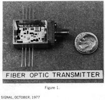 In
1975 Defense Systems was awarded NELC contracts for panel mounted modules,
Figure 1 on the left, followed by flat pack modules for circuit
board cards,
In
1975 Defense Systems was awarded NELC contracts for panel mounted modules,
Figure 1 on the left, followed by flat pack modules for circuit
board cards,
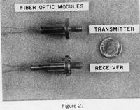 Figure
2 on the right. NELC viewed the panel-mounted modules as a retrofit
replacement for their electrical equivalent RG-8 or RG-58 coaxial connectors
on the back panel of current equipment. Manufacturing technology
contracts on these components were received from the Naval Air Development
Center (Warminster, PA) in 1976. These modules were developed
by John Kolling, then manager of the Hybrid Laboratory at Defense Systems
and his expertise in both hybrids and circuit design was instrumental
in establishing the Division’s reputation as a leading supplier
of fiber optic interconnect systems for military applications.
Figure
2 on the right. NELC viewed the panel-mounted modules as a retrofit
replacement for their electrical equivalent RG-8 or RG-58 coaxial connectors
on the back panel of current equipment. Manufacturing technology
contracts on these components were received from the Naval Air Development
Center (Warminster, PA) in 1976. These modules were developed
by John Kolling, then manager of the Hybrid Laboratory at Defense Systems
and his expertise in both hybrids and circuit design was instrumental
in establishing the Division’s reputation as a leading supplier
of fiber optic interconnect systems for military applications.
The R & D marketing of fiber optics was
done by myself and George Tkach (A P-3 Naval Reserve Flight Officer)
from Defense marketing. George established a close relationship
with the NELC Fiber Optic staff and particularly LCDR Jim Ellis who
provided liaison to NELC in an in-flight demonstration of fiber optics
interconnect for the A-7 Navigation and Weapon Delivery System.
This project was sponsored by the Naval Air Systems Command to demonstrate
the feasibility and effectiveness of fiber optics on an airborne military
platform. The fiber optic multiplexed system replaced 115
point-to- point channels of parallel wire cable with 13 simplex
channels and accumulated a total of 150 flight hours of failure free
operation.
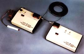 Our fiber optic modules were a key to winning contracts, so a fiber
optic data link demonstrator, Figure 3, was developed to market the
modules and the capability of fiber optics. It consisted of a
pair of transmitter and receiver modules and 100 feet of fiber optic
cable in which a 10 Mb/s data link was turned on and off by a hand held
push button switch. The switch activated a digital counter which
measured the time interval between the start and stop operation of the
switch. By successive operations of the switch, individuals
could measure their response time in milliseconds. Our customers would
like to test their reaction time on the system. We would end the
demonstration by disconnecting the fiber optic cable, moving the terminals
closer together and aligning the transmitter and receiver ports to show
the system could operate with no cable be at all. Our demonstrations
would frequently wind up with our customers rounding up their managerial
staff including VP’s to come and see the demonstrator.
The demonstrator was an effective demonstration of the small size of
100 feet of fiber optic cable as compared to its electrical coaxial
cable equivalent. In addition to its low size and weight its other
attributes included high data rates, longer transmission distances,
immunity to interference and a non-radiating transmission system, all
attractive to military applications, particularly airborne systems and
ground transportable links. Our initial production contracts were
won on those type systems.
Our fiber optic modules were a key to winning contracts, so a fiber
optic data link demonstrator, Figure 3, was developed to market the
modules and the capability of fiber optics. It consisted of a
pair of transmitter and receiver modules and 100 feet of fiber optic
cable in which a 10 Mb/s data link was turned on and off by a hand held
push button switch. The switch activated a digital counter which
measured the time interval between the start and stop operation of the
switch. By successive operations of the switch, individuals
could measure their response time in milliseconds. Our customers would
like to test their reaction time on the system. We would end the
demonstration by disconnecting the fiber optic cable, moving the terminals
closer together and aligning the transmitter and receiver ports to show
the system could operate with no cable be at all. Our demonstrations
would frequently wind up with our customers rounding up their managerial
staff including VP’s to come and see the demonstrator.
The demonstrator was an effective demonstration of the small size of
100 feet of fiber optic cable as compared to its electrical coaxial
cable equivalent. In addition to its low size and weight its other
attributes included high data rates, longer transmission distances,
immunity to interference and a non-radiating transmission system, all
attractive to military applications, particularly airborne systems and
ground transportable links. Our initial production contracts were
won on those type systems.
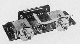 The first multi-year production program for the modules was a 100 MB/s
transmitter/receiver card, Figure 4, for the AN/UPQ – 3A Airborne
Data Multiplex system manufactured by the Defense Systems Division of
Sperry Univac in Salt Lake City. This was a fully militarized
system in which the modules were required to meet an operating environment
of – 55° C to 125 degrees C. Sixty transmitter/receiver
cards were required per system with distances up to 80 feet for the
airborne system and 1000 feet for the ground system. The
initial system used fiber optic bundled cable but was later upgraded
to small core single fiber cable. Acceptance testing was completed
for the system in 1977 with production beginning in 1978. At that
time it was the only production militarized airborne fiber optic system
in the U.S. Air Force.
The first multi-year production program for the modules was a 100 MB/s
transmitter/receiver card, Figure 4, for the AN/UPQ – 3A Airborne
Data Multiplex system manufactured by the Defense Systems Division of
Sperry Univac in Salt Lake City. This was a fully militarized
system in which the modules were required to meet an operating environment
of – 55° C to 125 degrees C. Sixty transmitter/receiver
cards were required per system with distances up to 80 feet for the
airborne system and 1000 feet for the ground system. The
initial system used fiber optic bundled cable but was later upgraded
to small core single fiber cable. Acceptance testing was completed
for the system in 1977 with production beginning in 1978. At that
time it was the only production militarized airborne fiber optic system
in the U.S. Air Force.
 A benchmark development/production award was received in 1980 for the
fiber-optic based Common Weapon Control System for the Ground Launch
Cruise Missile (GLCM) sponsored by the Joint (Navy/Air Force) Cruise
Missile Program Office. It was one of the first internationally
deployed weapon systems to be interconnected by fiber optics, which
was specified because of its ability to survive in a hostile environment
(including the effects of a nuclear event), its ease of deployment,
its immunity to electromagnetic interference and absence of radiated
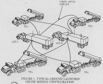
emissions. The GLCM system, Figures 5, consisted of two Launch
Control Centers (LCC) and four Transporter Erector Launchers (TEL) interconnected
by eight 300 meter cables each containing 3 full duplex digital communication
channels. Each cable carries multiplexed computer data,
digitized voice, and discrete signals in digitized form between elements
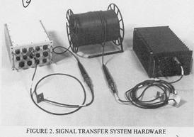
of the system. The Signal Transfer System hardware is shown in
the photograph of Figure 6 below left. The development contract
for the GLCM system was the largest fiber optic award of that time of
about $3 million followed by multi-year production awards starting in
1981 exceeding a total of $ 40 million dollars.
A benchmark development/production award was received in 1980 for the
fiber-optic based Common Weapon Control System for the Ground Launch
Cruise Missile (GLCM) sponsored by the Joint (Navy/Air Force) Cruise
Missile Program Office. It was one of the first internationally
deployed weapon systems to be interconnected by fiber optics, which
was specified because of its ability to survive in a hostile environment
(including the effects of a nuclear event), its ease of deployment,
its immunity to electromagnetic interference and absence of radiated
emissions. The GLCM system, Figures 5, consisted of two Launch
Control Centers (LCC) and four Transporter Erector Launchers (TEL) interconnected
by eight 300 meter cables each containing 3 full duplex digital communication
channels. Each cable carries multiplexed computer data,
digitized voice, and discrete signals in digitized form between elements
of the system. The Signal Transfer System hardware is shown in
the photograph of Figure 6 below left. The development contract
for the GLCM system was the largest fiber optic award of that time of
about $3 million followed by multi-year production awards starting in
1981 exceeding a total of $ 40 million dollars.
 Of
interest is that one of the technical evaluators of the proposal was
the NELC Fiber Optics staff from which we had received the initial $
25,000 contract for development of the transmitter module.
Of
interest is that one of the technical evaluators of the proposal was
the NELC Fiber Optics staff from which we had received the initial $
25,000 contract for development of the transmitter module.
Following this award, the group went on to
develop transmitter/receiver modules for the SAE standard High Speed
Data Bus (HSDB) which were low profile and suitable for mounting on
standard computer I/0 cards. In addition, an active fiber
optic coupler was developed for the HSDB under contract to McDonald
Douglas for use on the AV-8B , the proposed ATF-23 and other McDonald
fighter aircraft. Jim Herrmann designed the coupler and
was project engineer on the program which was awarded in 1988.
The active coupler extended the number of users beyond that achieved
with passive couplers.
The Fiber Optics engineering staff at the
time of the GLCM award besides myself was John Kolling, Jim Hermann,
Bill Davis, Ernie Griffith, Ross Starkson, Terry Thorvelson, and
Al Osberg. The Defense Marketer was Bill Sanda who received
a “Salesmen of the Year” award for winning the contract
against strong competition from the ITT-Roanoke Fiber Optics Division,
Lockheed Electronics Co. of Plainfield, NJ, Lockheed Missile and Space
Co. of Sunnyvale, CA and International Telephone. This was
an advanced development group responsible for engineering and demonstration
models which were passed on to design engineering for production systems.
Fiber Optics was just one of the activities of this group whose focus
had been on communication components and interconnect systems.
Members of the group were also active
participants on military and SAE standardization and working groups
on Computer interfaces and Local Area Networks. [ms]
![]()
5. More about Fiber optics by anonymous
The Marc Shoquist GLCM FO technology that
was fielded in Germany and along with Reagan convinced the Russians
that they we could outspend them leading to their downfall. This evolved
into the CVN77 RFOF IRAD and ultimately evolved to Rick Stevens F16/JSF
FO based Mission processor. LMCO is now building fiber optic back
panels for the F16 and several other Lockheed aircraft.
![]()
6. 1773: by Dick Erdrich
Marc, your fiber optics article above is a very good read.
I have fond memories of John Kolling - wish he could have counted
his Mondays down to zero.
I was aware of most of the projects that were mentioned,
but was only connected with John for the 1773 effort because of
my position as support engineer for the AN/AYK-14. I don't believe
we ever did any production release of a fiber Discrete and Serial
module - MIL-STD-1553B equivalent - but I thought that the design
was completed and could have been released if we had gotten a turn
on from the Navy.
We were very fortunate to have worked for a company like
UNIVAC during those years. Now that the division is controlled by
an aircraft company the opportunity to do wide ranging development
and research is gone unless it applies to their aircraft. There
are limited chances to work on something interesting but I did get
lucky. [rae]
![]()
7. SHINPADS contributed by Gene McCarthy
The SHipboard INtegrated Processing And
Display System (SHINPADS) Serial Data Bus is a high-speed digital interconnect
system designed for real-time Naval Electronic Systems. The SHipboard
INtegrated Processing And Display System is a concept that was originally
conceived by the Canadian Navy. ®SHINPADS is a registered trademark
of the Canadian Department of National Defence.
The Serial Data Bus (SDB) is used to interconnect devices
currently using interfaces such as Military Standard MIL-STD-1397 Input/Output
Interfaces or NATO standard interfaces such as STANAG 4146 (parallel)
and STANAG 4153 (serial).
The SHINPADS Serial Data Bus was specified, designed and
implemented by Sperry Univac Defense Systems. Sufficient growth margins
are incorporated by properly distributing functions between software,
firmware and hardware. The Serial Data Bus also provides for future
evolution to Fiber Optic Trans mission without changing operational
or system soft ware.
The concept is based upon the need to achieve a high degree
of survivability and operability in battle damage situations; system
reliability through use of reliable components, redundancy, and system
reconfiguration; low life-cycle cost by standardizing major system elements
and by reducing the complexity of interfaces; and improved performance
through the extensive use of digital computers, digital support equipment,
and a distributed system architecture.
The architecture of a system is largely influenced by the
techniques used to interconnect the equipment used in the system. Interconnection
techniques using MIL STD-1397 interfaces with various switching combinations,
duplexers, multiplexers, etc., have enabled the development of a variety
of system structures. The SHINPADS system has a distributed architecture
while other examples of military system architectures may be federated,
centralized or any combination of these architectures.
The simplicity of current standardized hardware interfaces has provided
system designers with a flexibility enabling the structuring of required
systems. However, the expansion of digital technology and the new system
requirements, such as those defined for SHINPADS, have created the need
for an efficient data bus system interconnect which allows complete
intercommunications between computers without great numbers of cables
and switches.
 Left, Richard L. Seaberg, Defense Systems vice president
and general manager, emphasizes Sperry Univac commitment to Canadian
military programs in an address to a group of 36 Canadian customer representatives
at Univac Park.
Left, Richard L. Seaberg, Defense Systems vice president
and general manager, emphasizes Sperry Univac commitment to Canadian
military programs in an address to a group of 36 Canadian customer representatives
at Univac Park.
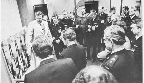 Right, Dick Olson explains operation of SHINPADS® serial
data bus access modules to visiting Canadian Department of Defence personnel
in an equipment demonstration following Mr. Seaberg’s remarks.
{Editor's Note: Gene McCarthy is circled on this snapshot.}
More than 200 customers have visited Defense Systems during the past
few months to view SHINPADS (Shipboard Integrated Processing and Display
System) demonstrations conducted in a specially prepared demo room.
The
demo room contained four militarized computers with a fifth system computer,
an AN/UYK-502, operated in a remote site. More Than 40 Groups from Nine
Countries have viewed the SHINPADS Demonstration.
Right, Dick Olson explains operation of SHINPADS® serial
data bus access modules to visiting Canadian Department of Defence personnel
in an equipment demonstration following Mr. Seaberg’s remarks.
{Editor's Note: Gene McCarthy is circled on this snapshot.}
More than 200 customers have visited Defense Systems during the past
few months to view SHINPADS (Shipboard Integrated Processing and Display
System) demonstrations conducted in a specially prepared demo room.
The
demo room contained four militarized computers with a fifth system computer,
an AN/UYK-502, operated in a remote site. More Than 40 Groups from Nine
Countries have viewed the SHINPADS Demonstration.
Many functions formerly centralized in computers have been
distributed throughout the subsystems. The interconnection of subsystem
elements by a data bus network provides for easier reconfiguration,
increases capacity for functional and physical expansion, and provides
ability for more direct intercommunication between any combinations
of subsystem elements.
With these combined features, the potential for fallback and survivability
in the event of loss of one or more subsystems is very high.
Conventional interconnection of military systems via point-to-point
wiring has many problems. Because of the sheer mass of cabling involved
one cannot afford to provide redundant hardware paths between all platform
subsystems. Therefore, the platform is vulnerable to outages caused
by failure of these dedicated cable paths.
The design and customer use of SHINPADS Serial Data Bus incorporates
role simulation, modeling and system protocol levels, the relationship
of software architecture to previous software architectures and reconfiguration
policy alternatives.
The SHINPADS concept is based on the extensive use of standard
digital computers widely distributed throughout a combat ship and connected
by a data bus. Theoretically, the data bus allows the digital computers
to serve as global resources capable of taking on any function because
of complete interconnection. The use of the data bus in SHINPADS also
provides a practical means for redundant physically separated interconnections
to improve system survivability.
Sharing a communication channel, such as a data bus, requires a blending
of competing demands for service to satisfy operational requirements.
The designers of a bus interconnect system must consider and ask questions
such as: “What is the average data transmission rate over a given
line?” ‘‘What is the peak data transmission expected
during any given time interval?” “How long will any user
have to wait to use the line?’’ “How will time critical
functions be granted access to the line? The systems designer must also
consider the question: “How can information be protected and controlled
in the distributed network?” The answers determine important parameters
in the bus interconnect system design. The SHINPADS Serial Data Bus
design team considered these questions and many more to identify the
important parameters for a naval combat system bus interconnect system.
The SHINPADS itself defined certain performance requirements which by
their nature required examination of naval combat systems in general.
Key SHINPADS Serial Data Bus features which distinguish
the Sperry Univac Defense Systems data bus from other buses include:
- Data Throughput
- Access Time
- Transmission Distance
- Number of Users Fault Tolerance
- Broadcast and Point-to-Point Addressing
- Bus Control
- Compatibility
Individual communication requirements for
a system such as SHINPADS were examined and a real throughput requirement
of 2.2 million bits per second (MBS) or less was determined. Although
2.2 MBS is a SHINPADS peak condition, the overall real throughput of
the bus was set at over 8 M BS to provide fast access time and room
for growth. Serial data busses, such as MIL-STD-1553B or Shipboard Data
Multiplex System (SDMS), have single channel real throughput capabilities
that are significantly less than 8 MBS, and higher rates can be achieved
only by duplicating channels.
Time critical access requirements were defined in terms
of critical message transfer rates. The extensive use of front end computers
for dedicated time critical functions such as signal processing tends
to reduce overall access time requirements, although access times less
than 500 microseconds are still needed for some systems. The SHINPADS
Serial Data Bus guarantees specified access times.
The maximum length of the bus was specified to be 300 meters.
Three hundred meters was selected because it is sufficient for shipboard
applications. Point-to-point interface connections to the SDB are made
by stub cables of up to 30 meters. The SHINPADS system required in excess
of 90 bus connections. However, the maximum number of connections specified
for the SHINPADS bus is 256 to provide room for growth. Bus systems,
such as MIL-STD-1553B, SDMS, and others, provide a user addressing capability
ranging from less than, to significantly more than 256. The number selected
is a “trade-off” between the amount of performance required
and our adequate number of user addresses. Excessive addressing capability
increases the overhead factor which limits throughput.
The shipboard environment requires survivability of system
functions, not only for single failures but for multiple failures. The
bus system contains up to six redundant transmission cables which can
be rapidly utilized in case of problems.
The SDB is capable of interconnecting existing sub systems
with minimum modifications to the sub systems. Existing subsystems covered
by this requirement are characterized by the extensive use of MIL-STD-1397
interfaces and the characteristic of exchanging information through
the use of variable length messages. A significant feature of MIL-STD-1397
interfaces is that the interface protocol is simple and only controls
the transmission and receipt of information and does not operate on
the content of the data word.
Fundamental to the SHINPADS concept is the use of standardized
interfaces. The use of standardized interfaces in digital systems has
been a goal of Sperry Univac Defense Systems since the development of
the U.S. Navy Tactical Data System in the 1950’s. Standard interfaces
must have special qualities to have a useful long life since many of
the peripherals interconnected in the future will not have been designed
when the standard interface is specified.
The SHINPADS Serial Data Bus design was based upon an understanding
of the interconnect system philosophy which forms the foundation for
MIL-STD-1397 interface options. This is important because MIL-STD-1397
is currently being used on most, if not all, Navy equipment developments.
However, the bus was also specified with an eye to the future. A large
growth margin was designed into the system to allow for future considerations.
The implication is that distributed system architectures are not only
possible, but are now becoming practical for applications requiring
a network of small interconnected computers.
As technology advances, higher data transmission rates
will be possible. Therefore, the SHINPADS protocol was designed so high-speed
transmission systems can be used without changing the protocol of user
system software. For example, when fiber optic technologies become cost
effective, the SHINPADS SDB can be upgraded.
[efm]
![]()
8. Communications Systems by Larry Debelak
Ole: Here are some links to briefs that show the history since the NTDS to 1997 Chart you slipped under my door--What is missing are the Non-Navy systems and the classified systems to include the antenna couplers [e.g. Air Force SMA], Project Spring [Salt Lake], Israel Project 6977 [Eagan], the Salt Lake DOD [Micro wave TDL] and the commercial Univac Switch product story [Salt Lake]---Bruce Olson or Marc Shoquist should be able to fill these in----and Harry Wise should have the Eagan Remote Control Communications switch he put in unmanned Navy communication sites in the Southeast that were the fore runner of the MATCALS/ABCCC switch that Joe Pobiel & Marc Shoquist have the book on.
Also Lauren Cady worked on the Home grown Automated Voice Telephone Switch system for the Eagan facility.
This along with the ABCCC JTIDS, TMRC/ASOC Data links and the SOS Po Sheng JTIDS/FO based network fill out your chart and could provide quite
an impressive legacy for the Rick Udicious newly created Communications and Networks Business Unit. Now we just have to fill the vision with
a win on AMF JTRS, evolve the LCS CRR success to other Surface ships and leverage the Owego US101 COSITE/UHF SATCOM subsystem to airborne
platforms--Then the Univac to LM Communications and Networks Legacy story will be complete and I can retire. thanks.
We also used Harry's/Joe's/Jack Schaubert's switch, Joe's/Dr. Don Kleven's Digital Voice SW with silence detection and Steve Andersen's
SHINPADS/FDDI/SAFENET/ATM/InterPhase experience that along with ABCCC Automated Communications Selector GUI's was the foundation for the NSSN
CRAD effort with NUSC Newport/Groton [Now NUWC Newport] & PEO SUB.
From this success [Bob Siegfried was the Network CRAD lead that simultaneously hosted the Q-70 Combat Control/Sonar & Voice over IP with 5 MS latency],
I got the first PEO SUB $3M Contract for COTS Radio room prototype that became the EB Virginia CSRR, LCS and the Current PMW 770 CSRR contracts
for all Sub Classes with an unprecedented 3 years of Congressional Plus ps. [LF Debelak]
![]()
9. Hyperchannel before internet by Jim Andrews
My recollections from the late 80s:
In the 1980’s, Defense Systems occupied many locations in the
Twin Cities.
Plant 8 was the home of the Information Systems mainframe 1100 systems (DC, DS, DE) and a VAX computer (ENGVAX) while Corporate Square
was home to several Engineering VAX computers (BIGSKY, ALTA, …) along with Apollo and Sun workstations.
There was no internet at the time, so couriers drove vans between the sites to move supplies, deliver computer jobs and deliver communications at scheduled times daily.
Data transfer was done by passing magnetic tapes and printouts between sites each day. The result was slow turnaround time for many processes.
I was working for the Systems Support group in Corporate Square where projects ATF, ABCCC, and CP-901 were being worked.
The company had recently purchased “Hyperchannel” equipment from a local company called Network Systems Corporation (NSC).
NSC had been co-founded by James Thornton and Peter D. Jones but its roots go back to Engineering Research Associates (ERA) which became UNIVAC.
James Thornton and William Norris were employees of ERA, then Univac.
![]()
In 1958, William Norris and a few other former ERA engineers including Thornton left UNIVAC to start Control Data Corporation (CDC). Six years later, Thornton left CDC to start NSC with a mission to network remote computers over dedicated phone lines. The company developed its own protocol for transmitting the data then built hardware adapters for each computer model that connected the computers to the phone line and handled the encoding, transmission and decoding of data between the two computers.
I was given the assignment to get Hyperchannel capability operational between sites and then develop applications which would be useful to the various projects. This required interfacing with Network Systems personnel and the administrators of the various Engineering computer systems and Information Technology computer systems to get the equipment installed and operational. My first application was to transfer ASCII files between the VAX and the 1100 system which allowed the projects to transfer their source code maintained on the VAX computers to the 1100 system for CMS-2 compilation and allowed VAX print files to be sent to 1100 for printing on the high speed printers.
This was followed by an application to transfer binary files from one VAX to another VAX or to the 1100 system which allowed backing up VAX files on the 1100 and returning compiled object code from the 1100 system to the target computer where it would be executed. Once operational, these applications eliminated the dependency on the courier service between plants and reduced turnaround time on computer runs for the various projects.
I became the Administrator of the Hyperchannel system and in this capacity I assisted users and provided usage reports to project management. The Hyperchannel stayed in productive use moving data between sites over the dedicated phone line until 1993 when internet capabilities using TCP/IP proved to be more efficient and cost effective. Once the projects began using the internet, the Hyperchannel equipment was taken out of service. By 1995, Network Systems Corporation could no longer compete with other internet equipment providers, and they merged with another company. With that the era of the Hyperchannel ended. [Added to the anthology May 4, 2025 by LABenson]
In this Chapter
- Introduction [left]
- Point to point
- Low Level Serial Interface
- Fiber Optics
- More about Fiber Optics
- 1773
- SHINPADS
- Communications Systems
- Hyperchannel by Jim Andrews
Chapter 44 edited 7/13/2025.
![]() |
Home, Pg 1 |
Our Legacy, Ch 1 |
People |
Locations |
Engineered |
Computers |
Systems |
Contacts and Links |
Site Map, Pg 0 |
|
Home, Pg 1 |
Our Legacy, Ch 1 |
People |
Locations |
Engineered |
Computers |
Systems |
Contacts and Links |
Site Map, Pg 0 |
Copyright ©2025, LABenson for the VIP Club. All Rights Reserved; Hosted on www.webhostinghub.com since 2011.